Phases¶
A phase is one bounded equipment activity: charge, heat-to-temp,
drain, pressure-test. It's the leaf of the ISA-88 procedural
hierarchy: operations and unit procedures sequence phases, and recipes
sequence unit procedures.
Every phase template is authored as one Sequential Function Chart (SFC)
per ISA-88 state: Running always, plus optional charts for Holding,
Restarting, Stopping, Aborting, Resetting. The platform manages
the lifecycle states. You write the charts that drive equipment when
the phase is in each state.
This page covers what an SFC is and how it wraps the ISA-88 lifecycle, how to author a phase template in the visual editor or YAML, every chart construct available (steps, transitions, divergences, loops), and the failure archetypes every phase falls into.
For the level above (composing phases into operations, unit procedures, and recipes), see Recipes.
Integrators: see the API Reference for the REST equivalents of the actions on this page.
What an SFC is¶
A Sequential Function Chart is a state machine drawn as a directed graph of steps (rectangles) and transitions (horizontal bars with guard conditions written next to them).
graph TD
    Start([initial]) --> S1[heat]
    S1 -->|"PV >= target_temp"| S2[hold]
    S2 -->|"elapsed_seconds >= hold_time"| S3[cool]
    S3 -->|"PV <= cool_target"| Done([done])
Every scan cycle, the SFC engine:
- Looks at the active step (one and only one step is active at a time in a linear chart).
- Runs that step's
actionSTblock — Structured Text that reads and writes tags. - Evaluates every outbound transition from the active step. If any guard condition is true, deactivates the current step and activates the next one.
- Repeats next scan.
The execution loop is scan-based, like a PLC. The scan rate is fixed (typically 100–500 ms depending on the runtime configuration). Step actions don't block. They're snippets of ST that run once per scan. They are not coroutines.
SFC vs ladder vs raw FBD vs ST¶
If you're coming from a different IEC 61131-3 environment:
| SFC | Ladder | FBD | ST routine | |
|---|---|---|---|---|
| Active execution | Exactly one step active at a time per branch | All rungs evaluated each scan | All blocks evaluated each scan | All statements run sequentially each scan |
| State persistence | Implicit in which step is active | Explicit via internal coils/memory | Explicit via FB internal state | Explicit via static variables |
| Sequencing logic | Built into the chart | Encoded in coils + branching rungs | Encoded in FB chains + state machines | Encoded in IF/CASE/state vars |
| Best for | Recipe steps, batch sequencing, startup/shutdown | Interlocks, permissives, latches | Continuous calculations, control loops | Math, loops, complex data |
For a phase like "fill, heat, agitate, drain", SFC is the natural language. The chart literally looks like the steps an operator would write on a procedure sheet. That's not a coincidence. SFC was designed for procedural sequencing.
Why every phase here is SFC: ISA-88 phases are inherently sequential. They move material through a series of states. Encoding them in ladder or raw FBD works but obscures the sequence. SFC makes the procedural intent visible in the source. Flat (non-SFC) ST programs are not accepted as phase bodies. Every phase state that runs must be expressed as a chart. This enforces visible step state and makes phases safe to pause, resume, and inspect from the HMI.
Diagram notation¶
This page uses two visual languages and you'll see both as you author. The mermaid diagrams here teach the abstract patterns. The SFC editor (System UI → Equipment Library → Phases → Edit SFC) is where you draw them. The two render with the same conventions (rectangles for steps, horizontal bars for transitions). A mermaid chart on this page should therefore map one-to-one onto what you see in the editor.
Each construct below is paired with a small mermaid example and, where applicable, the matching editor screenshot.
Steps and transitions¶
Rectangles are SFC steps. The horizontal bar (or labelled arrow,
in mermaid) between two steps is a transition carrying a
Structured Text guard condition. Stadium shapes (([initial]),
([done])) mark the chart's entry and exit. Guards are quoted in
mermaid because they often contain operators (>=, &&) that the
renderer would otherwise parse as arrow syntax.
graph TD
    Start([initial]) --> S1[fill]
    S1 -->|"PV >= setpoint"| S2[hold]
    S2 -->|"elapsed >= dwell"| Done([done])
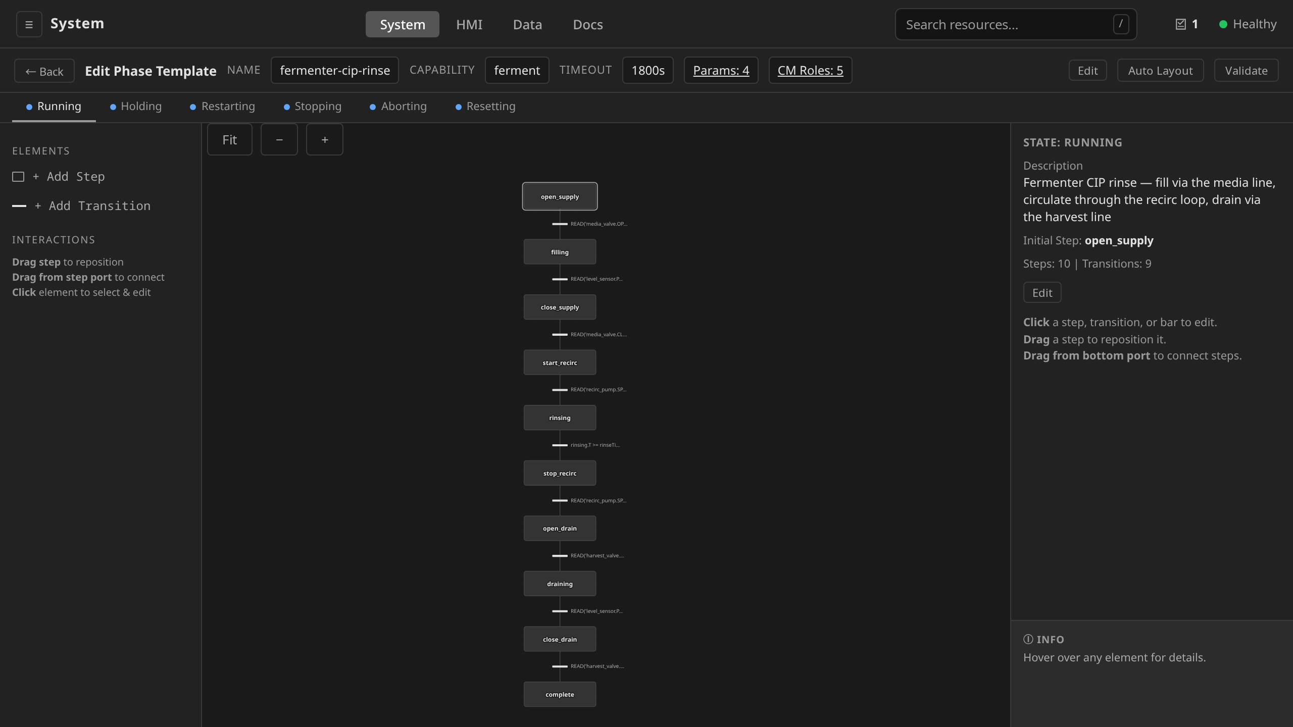
In the editor, each step is a rounded rectangle (the initial step has a double border) and each transition is a short horizontal bar with its condition rendered to the right:
Selective divergence and convergence¶
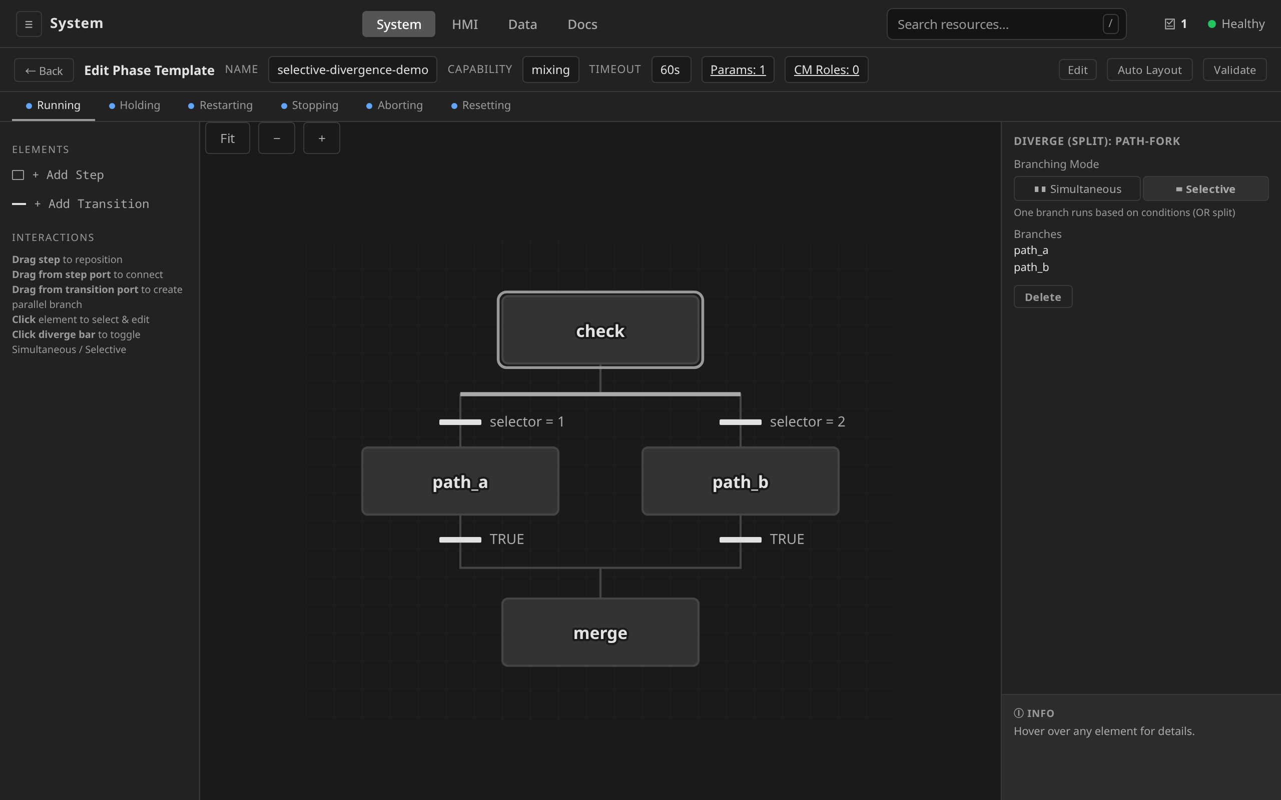
When one step has multiple outbound transitions, the chart is a selective divergence: whichever guard becomes true first wins, and only that branch activates. Multiple branches merging back into one step is a selective convergence: any branch's completion advances the chart.
graph TD
    Check[check] -->|"selector = 1"| A[path-a]
    Check -->|"selector = 2"| B[path-b]
    A --> Merge[merge]
    B --> Merge
In the editor, a divergence is rendered as a wider horizontal bar fanning into multiple steps. Click it and the inspector shows the branching mode (Selective vs Simultaneous):
Simultaneous divergence and convergence¶
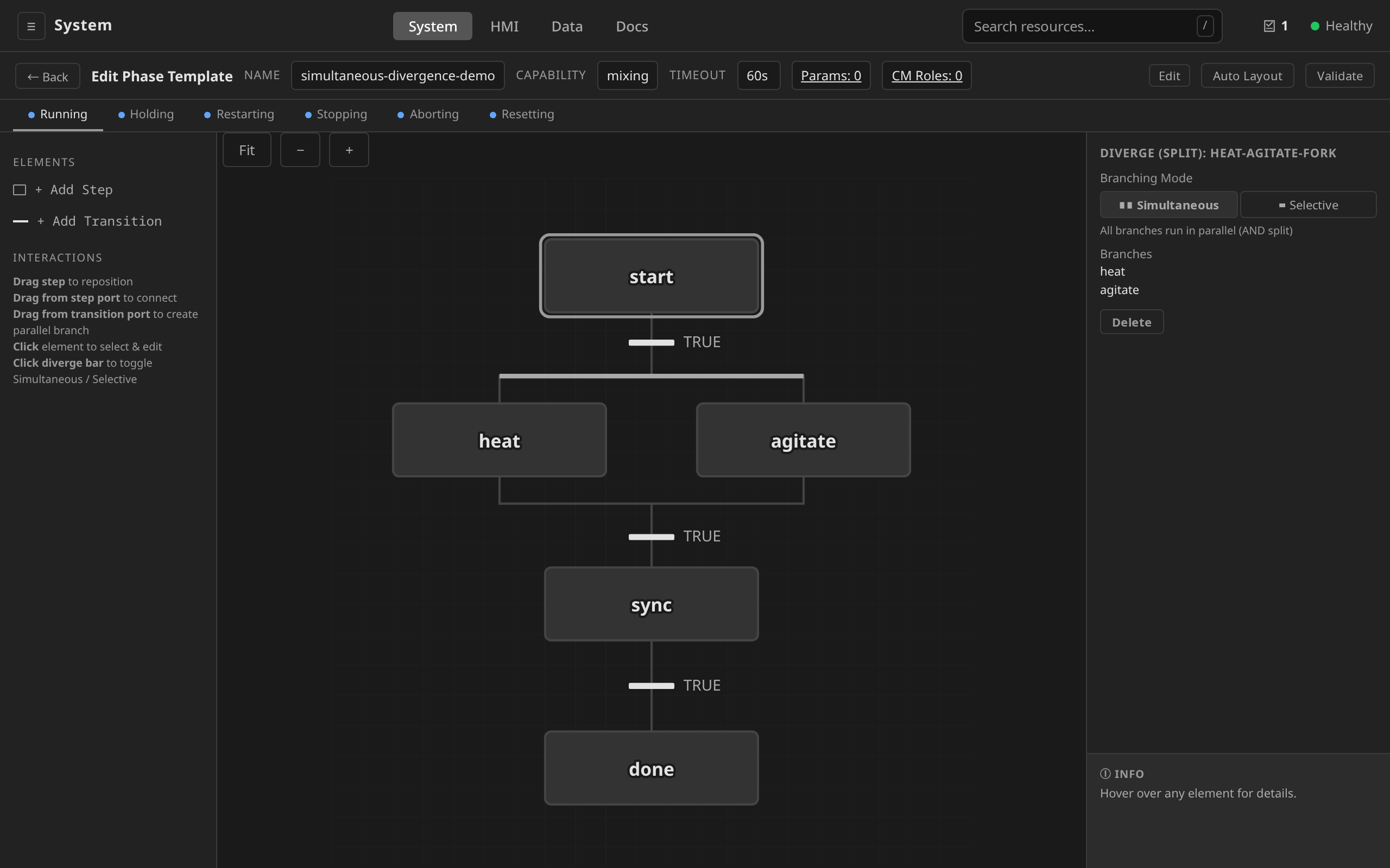
Parallel branches drawn from one step to multiple steps with no guards are a simultaneous divergence: all branches activate at once. They re-merge at a simultaneous convergence, which only advances after every branch has completed.
graph TD
    Start[start] --> A[heat]
    Start --> B[agitate]
    A --> Sync[sync]
    B --> Sync
    Sync --> Next[next-step]
In the editor this uses the same divergence bar as the selective case above, with Branching Mode: Simultaneous in the inspector:
Back-edges (loops)¶
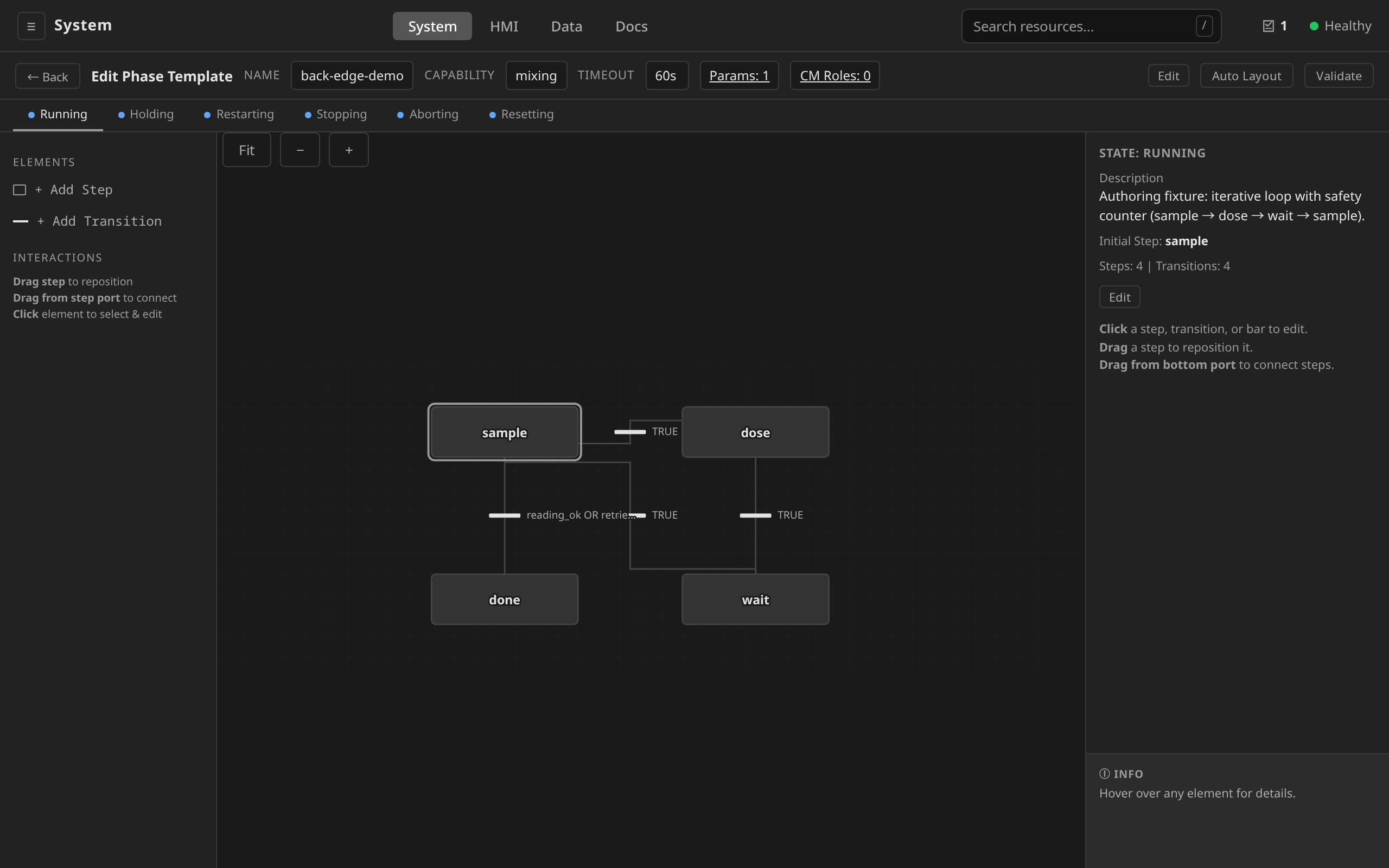
An arrow from a later step back to an earlier one is a loop, used in iterative phases (e.g. dose-and-sample-until-pH-stable). Always pair a back-edge with a safety counter (see Iterative phases with safety counter).
graph TD
    Sample[sample] -->|"reading_ok"| Done([done])
    Sample -->|"!reading_ok && retries < max"| Dose[dose]
    Dose --> Wait[wait]
    Wait --> Sample
In the editor, the back-edge appears as an arrow returning from a
later step (wait) to the loop's re-entry step (sample). The exit
transition leaves sample toward done:
Priority transitions¶
When multiple guards on the same step are simultaneously true, the
SFC engine evaluates outbound transitions in ascending order of
priority and fires the first one whose guard is TRUE. So a
lower number wins: priority 0 is the preferred path, priority
1 is the next fallback, and so on. By convention the preferred /
safety guard takes 0 and routine sequencing guards take a higher
number.
graph TD
    Run[heating] -->|"PV >= safety_limit  (prio 0)"| Abort[abort-cool]
    Run -->|"PV >= setpoint        (prio 1)"| Done([done])
The transition inspector exposes the Priority field directly:
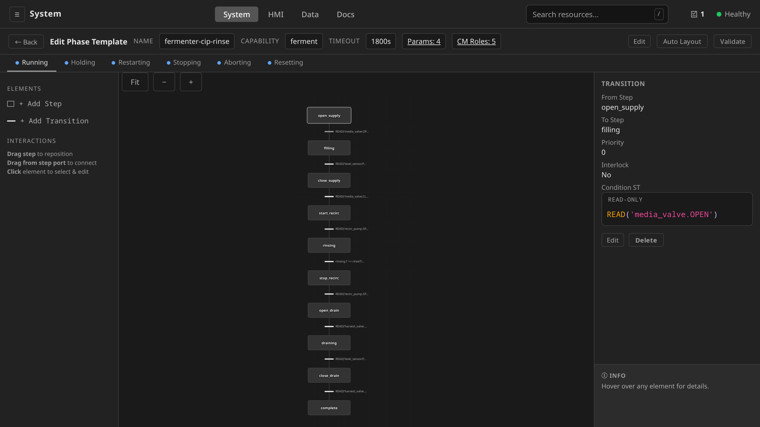
The ISA-88 state machine wrapping¶
Each running phase has two layers of state:
- The SFC state — which step in the chart is currently active. Authored by you as a phase template.
- The ISA-88 lifecycle state — Idle, Running, Held, Stopped, etc. Managed by the platform. You don't write this. It wraps your SFC.
The ISA-88 layer answers "what should the SFC engine do right now",
and the SFC engine drives your chart accordingly. When the operator
issues a Hold command, the ISA-88 layer transitions from Running
to Holding to Held and the SFC engine pauses your chart. When the
operator issues Restart, it goes Held → Restarting → Running and
your chart resumes from the same active step.
Cloud-Native DCS implements the ISA-88 13-state model:
stateDiagram-v2
    [*] --> Idle

    Idle --> Running: Start

    Running --> Complete: SC
    Running --> Holding: Hold
    Running --> Stopping: Stop
    Running --> Aborting: Abort
    Running --> Pausing: Pause

    Pausing --> Paused: SC
    Pausing --> Stopping: Stop
    Pausing --> Holding: Hold
    Pausing --> Aborting: Abort

    Paused --> Running: Resume
    Paused --> Stopping: Stop
    Paused --> Holding: Hold
    Paused --> Aborting: Abort

    Holding --> Held: SC
    Holding --> Stopping: Stop
    Holding --> Aborting: Abort

    Held --> Restarting: Restart
    Held --> Stopping: Stop
    Held --> Aborting: Abort

    Restarting --> Running: SC
    Restarting --> Stopping: Stop
    Restarting --> Holding: Hold
    Restarting --> Aborting: Abort

    Complete --> Resetting: Reset

    Stopping --> Stopped: SC
    Stopping --> Aborting: Abort

    Stopped --> Resetting: Reset
    Stopped --> Aborting: Abort

    Aborting --> Aborted: SC

    Aborted --> Resetting: Reset

    Resetting --> Idle: SC
Notation:
- Solid arrows labelled with command names (
Start,Hold,Stop,Abort,Pause,Resume,Restart,Reset): operator or controller-driven transitions. These are the eight commands available viadcs command Batch <name> <Command>and on the batch command bar. Commands target the Batch, which propagates them down to its phases (phases are not commanded directly). SC(State Complete) — internal transition emitted by the controller when a transient state's action finishes. You don't issue these manually. They fire automatically when, for example, the Holding state's logic finishes (vent, close inlets, etc.) and the state advances to Held.
The six "transient" states (Holding, Restarting, Pausing,
Stopping, Aborting, Resetting) execute platform-defined actions
and then auto-advance via SC. The seven "stable" states (Idle,
Running, Held, Paused, Complete, Stopped, Aborted) wait
for an operator command.
The holdingChart is also armed at the edge
Your holdingChart is the procedural safe-state response, and the unit
runtime stages it as a partition-triggered local-hold program
(ADR 0008). If the control plane
becomes unreachable mid-phase, an SFC engine embedded in the runtime runs
the same holding chart locally to drive a deliberate sequenced safe
state. The alternative was freezing the equipment wherever the partition
caught it. Because it must run with no cluster round-trip, an edge-armed
chart may only READ/WRITE the unit's own control-module tag space.
Cross-unit and control-plane-only data are out of reach.
make lint-edge-armable enforces this over the
examples. A chart that violates it falls back to the unit's
safeStateChart baseline and the operator surfaces a warning. Keep holding
logic self-contained to the phase's declared cmRoles and it is edge-armable
by construction.
The same reasoning governs what an edge-armed chart may do. Eleven builtins
cannot run during a partition, because each needs something the partition
has taken away: PROMPT, PROMPT_CHOICE and PROMPT_VALUE need an
operator, AWAIT_RESULT needs the gateway the external system delivers
through, MODE needs the Kubernetes API, COMMAND and STEP_ACTIVE need
the control plane that drives the phase state machine, and CALL_SERVICE,
MTP_COMMAND, MTP_STATE and MTP_COMMAND_ENABLED need a session to
another machine. Writing one of them into a holdingChart is still
legitimate, since the chart runs on the control-plane path in every case
except a partition. The runtime simply will not arm that chart. The phase
falls back to the unit baseline, and you are told at phase start.
Learning it mid-partition is what the early refusal prevents.
The arming lives in the runtime's memory, so it goes with the pod. A phase
that is Running re-arms on its own, because the chart it is executing
reaches the runtime anyway. A phase resting in Held is still engaged and
still entitled to its own program, and it executes nothing that would
notice a replacement. The control plane therefore watches the runtime pod
on its behalf
(#1404). A runtime that is rescheduled, evicted or OOM-killed under a Held
phase comes back carrying only the unit baseline, and the phase's own chart
is staged again as soon as the replacement is ready. Until that moment the
phase still has baseline cover.
| State | Stable / transient | Your SFC chart | Operator can... |
|---|---|---|---|
| Idle | Stable | Not running | Start |
| Running | Stable | Active and advancing | Hold, Pause, Stop, Abort |
| Pausing | Transient | Suspended (last action persists) | (waits for SC) |
| Paused | Stable | Suspended | Resume, Hold, Stop, Abort |
| Holding | Transient | Frozen, platform runs holding-state action | (waits for SC) |
| Held | Stable | Frozen | Restart, Stop, Abort |
| Restarting | Transient | About to resume from where it was held | (waits for SC) |
| Stopping | Transient | Platform runs stopping-state action | Abort |
| Stopped | Stable | Halted at a clean stopping point | Reset, Abort |
| Aborting | Transient | Platform runs aborting-state action (emergency cleanup) | (waits for SC) |
| Aborted | Stable | Halted via emergency path | Reset |
| Complete | Stable | Reached final step naturally | Reset |
| Resetting | Transient | Returning to Idle | (waits for SC) |
Writing a restartingChart: the resumed step will not re-command anything
A Restart resumes the action chart at the step it was held on, and a step
whose action had already finished is restored as active-and-done. The
engine will not replay it, because a step action can prompt an operator,
write a line into the batch record, or call a service on a skid. So if your
holdingChart shut a valve the resumed step needs open, the
restartingChart is the only thing that will open it again.
That makes a restarting chart written for one step wrong for the others. Use
STEP_ACTIVE('<step>') to branch on where the phase was held. It names
a step of the action chart and is available in every transitional chart
(ADR 0047,
Procedural SFC dialect):
IF STEP_ACTIVE('open_media') THEN
  WRITE('media_valve.CMD', TRUE);   (* held mid-charge: reopen the inlet *)
END_IF;                             (* held during the settle: leave it shut *)
Admission rejects a name that is not a step of the action chart, because a
wrong name never fails at run time. It is simply FALSE. make
lint-restart-posture catches the same mistake in the example corpus before
it reaches a cluster, alongside the unguarded WRITEs this warning is about.
The key intuition: your phase template is a chart of process
steps that runs only when the wrapping ISA-88 state is Running.
All the other states are either stable resting points (Idle,
Held, Complete, Stopped, Aborted) where your chart isn't
executing, or transient platform-managed states that handle the
mechanics of holding/stopping/aborting cleanly.
Authoring a phase template¶
Phase templates can be authored three equivalent ways, and the platform stores the same data whichever path you take:
- UI — the visual SFC editor at
/system(drag-and-drop steps and transitions, inline ST editor, live validation, per-state tabs) - CLI —
dcs apply -f file.yamlagainst a YAML manifest - API —
PUT /api/v1/sites/{site}/phasetemplates/{name}
The YAML schema below is the canonical serialization. The UI reads and writes exactly these fields, and the API accepts the same shape as JSON.
Before you start
An SFC is a state chart. Whether you drag it in the UI or hand-write YAML, sketch the chart on paper first (steps as boxes, transitions as labeled arrows). Trying to compose it top-down without a chart in mind usually produces tangled transitions. Use the worked cip-heat-and-hold example farther down as a starting template.
Opening the visual SFC editor¶
Phase templates are managed in the Equipment Library under the Phases section:
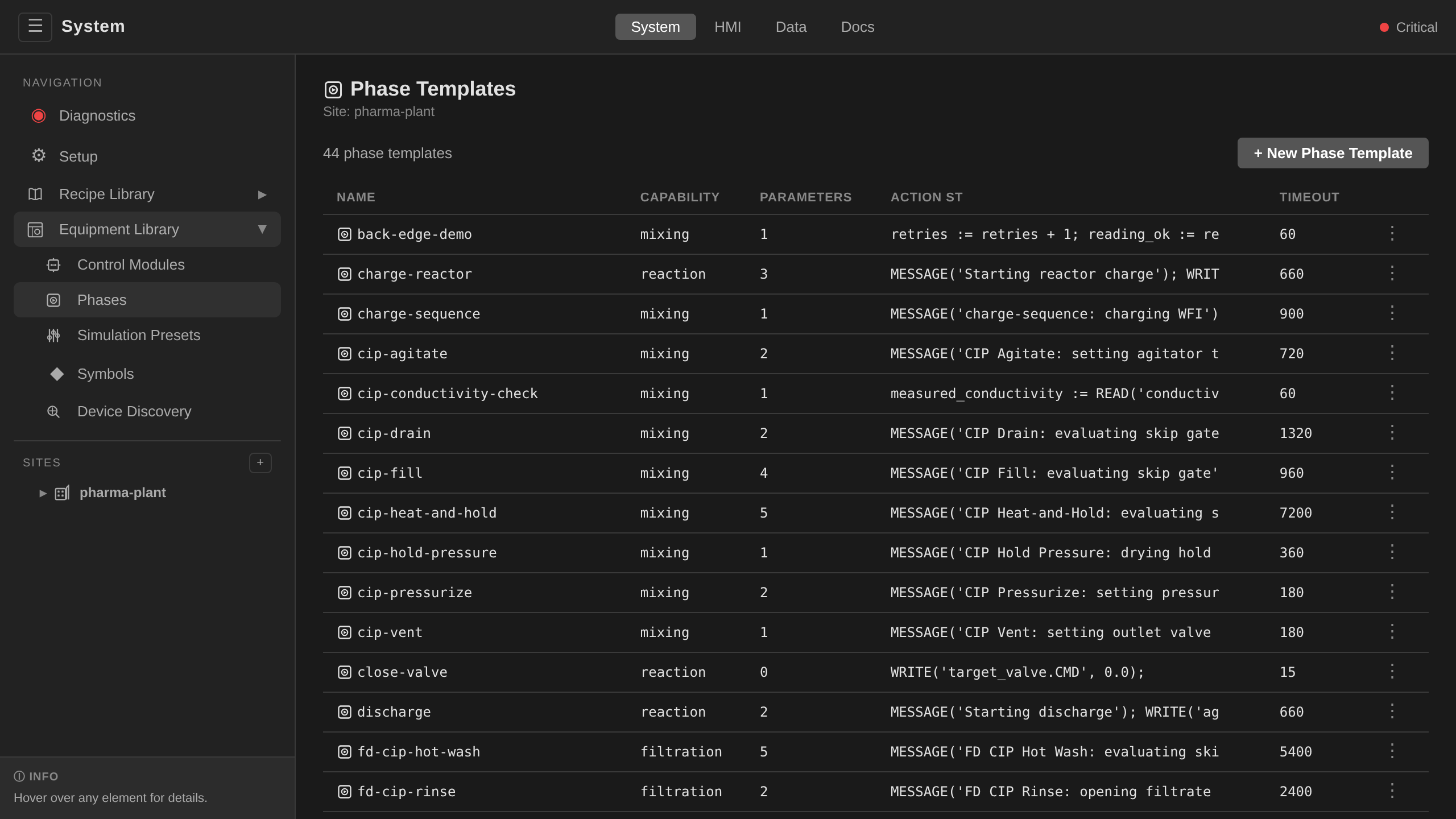
Open the editor:
- From a phase template —
/system→ Equipment Library → Phases → pick a site → click a template row → Edit SFC (top-right). The same path works for operation and unit-procedure templates (sidebar under each site).
Editor layout¶
The editor has three zones:
- Left — Elements palette.
+ Add Stepand+ Add Transitionbuttons. A brief INTERACTIONS cheat-sheet (drag to reposition, drag from a step's bottom port to connect, click to select & edit). - Centre — Canvas. Steps rendered as rounded rectangles with a
double border for the initial step. Transitions rendered as short
horizontal bars with their condition label to the right. Zoom
controls (
Fit,-,+) in the top-left corner. - Right — Properties. Context-sensitive:
- With nothing selected: chart summary (initial step, step count, transition count, description, top-level Edit for chart metadata).
- Step selected: name, description, initial-step flag, Wait for Action setting, timeout, inline ST code editor, Edit / Delete buttons. (Wait for action replaced the IEC 61131-3 action qualifiers, so there is no qualifier dropdown.)
- Transition selected: from-step, to-step, priority, inline ST condition editor.
- Divergence selected: type (Simultaneous / Selective), branches, convergence step.
The top toolbar has Auto Layout (re-flows the chart using the layered layout engine), Validate (runs the same checks as the API and lists any errors in a dialog), and an Edit button for the chart's top-level fields (name, capability, timeout, parameters, CM roles).
Both browser editors run below: the SFC editor opening a phase chart
and Validate returning its persistent "✓ Chart valid" marker,
then the FB control-module editor beside it (the negative half too: a
FOR loop is refused with a located diagnostic).
Per-state tabs¶
For phase templates only, the editor shows a row of tabs above the canvas, one per ISA-88 state: Running, Holding, Restarting, Stopping, Aborting, Resetting. Each tab holds a separate chart. Click a tab to edit that state's chart independently. Tabs with a filled dot already have a chart defined. Operation, unit-procedure, and recipe procedure templates show no tabs. Each of those has a single chart.
Editing a step's action¶
Click a step to see its read-only properties: name, description, initial-step flag, wait-for-action setting, timeout, the control-gap verdict, and the Action ST body.
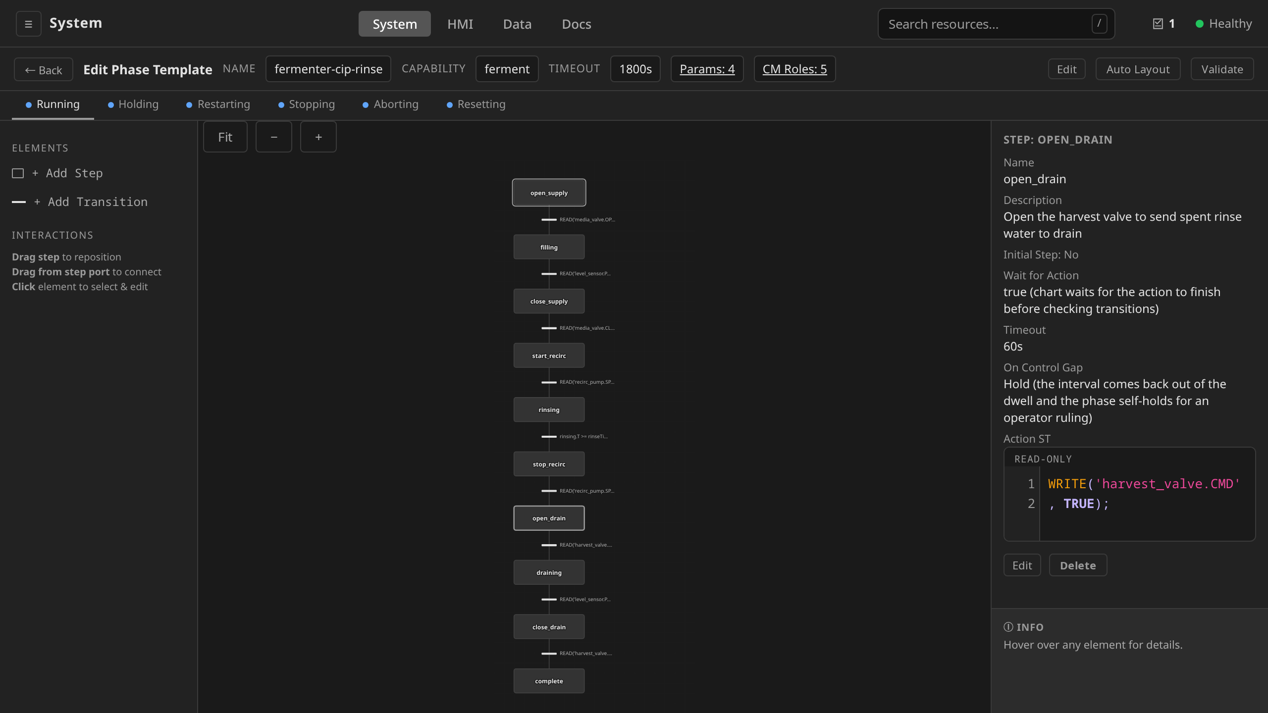
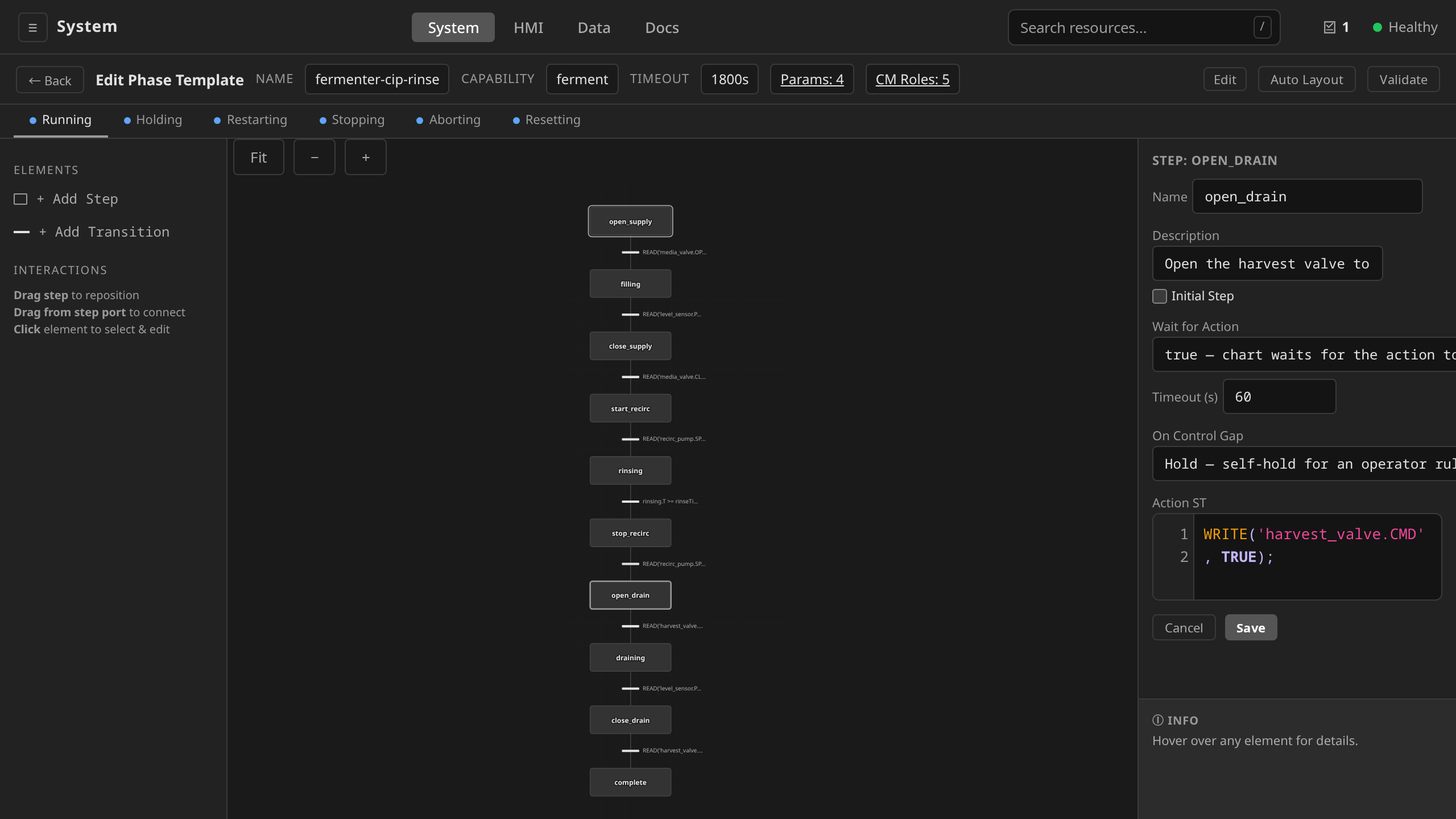
Click Edit and the right panel becomes an editable form. The Action
ST textarea highlights IEC 61131-3 syntax for keywords (VAR, IF,
THEN, END_IF), built-ins (READ, WRITE, MESSAGE, PROMPT,
COMMAND), and literals. ST that parses but fails validation is
refused with errors rendered inline under the editor. The panel's
Save applies the step to the working copy (Cancel discards).
The chart itself persists when you hit the toolbar Save, which
validates the whole template server-side.
Editing a transition's condition¶
Click the transition bar and the right panel switches to its From Step, To Step, Priority, and Condition ST.
Click Edit to edit the Condition ST. An empty condition fires as
soon as the source step's action completes. Priority is evaluated
lowest-first. Use 0 for the preferred path when several transitions
leave the same step.
Drawing the chart¶
- Add step — click
+ Add Stepin the palette, or drop one on the canvas by clicking an empty area after selecting the step tool. - Reorder / reposition — drag a step anywhere on the canvas. Hold to start the drag, and the chart lines re-route automatically.
- Connect steps — hover a step → two ports appear (top = inbound, bottom = outbound) → drag from the bottom port onto the target step. A transition is created with an empty condition. Click it to edit.
- Two exits to one step — draw the same connection a second time. Both legs stay on the canvas and each carries its own condition. The new leg is placed one priority behind every exit the step already has, so the exits already drawn keep their precedence and the new one is the fallback. This is the shape a process endpoint and its timeout take: the measurement ends the step when it is reached, and the timer ends it when the measurement never arrives. A leg with no condition is unconditional, so the editor says which priority it used and that the leg still needs a condition.
- Delete — select an element and press the Delete key, or use the Delete button in the right panel.
Declaring parameters and process outputs¶
A phase records two distinct kinds of values in the BPR, and ISA-88 keeps them separate on purpose:
- Process Parameters (Part 1 §6.3.3) — the setpoints the recipe commands into the chart. They flow in as ST variables, and the chart reads them to drive control logic.
- Process Outputs (Part 1 §6.3.3) — values the chart's ST writes: paired actuals (a measurement of the input that was just commanded), totalisers, integrated quantities, derived quality metrics, environmental observations.
Declare each kind in its own list: spec.parameters for inputs,
spec.outputs for everything the chart records. The chart's ST
assigns to declared output names like any ST variable. The runtime
snapshots the final value of each declared output from the ST
environment at phase terminal time.
| Kind of value | Where to declare | Author work |
|---|---|---|
Recipe-commanded input (e.g. target_temp, enable_jacket) |
parameters[] |
Read it like any ST variable; it's the setpoint |
| Anything captured for the BPR (paired actual, totaliser, integral, peak) | outputs[] |
Assign to the declared name in the chart's ST: <name> := <expr>; |
For paired actuals (commanded setpoint + measured counterpart), declare
both: an input AND a separate output. The convention is to suffix the
output name with _actual:
parameters:
  - name: target_temp
    type: REAL
outputs:
  - name: target_temp_actual
    type: REAL
    description: "Sensor PV at terminal time"
The chart's ST then writes the actual at the appropriate step:
target_temp_actual := READ('temp_sensor.PV');
Tag paths in READ() use direct CM-role-relative strings (e.g.
temp_sensor.PV). The leading role segment is validated against the
PhaseTemplate.cmRoles list and the target Unit's cmRoles map.
To capture a tag-bound output only on successful completion, only
assign in the chart's Done (or equivalent) terminal step. To capture
on any terminal state, also assign in the stopping/aborting charts.
The chart itself expresses what was previously a captureOn field.
Names must be unique across parameters[] and outputs[] within a
single template. The recipe instantiator rejects collisions at batch
creation time.
Not yet in the UI
The phase template parameter editor in /system does not yet
surface a separate output editor. Until the editor is updated,
declare outputs in the YAML manifest and apply via dcs apply.
The controller picks them up the same way regardless of
author path.
apiVersion: procedural.dcs.io/v1alpha1
kind: PhaseTemplate
metadata:
  name: charge-and-hold
  namespace: site-demo
spec:
  capability: mixing
  timeoutSeconds: 1800
  cmRoles:
    - role: temp_sensor
      moduleType: sensor
    - role: flow_meter
      moduleType: sensor
    - role: pressure_sensor
      moduleType: sensor
  # Process Parameters — recipe-commanded setpoints (inputs).
  parameters:
    - name: enable_jacket
      type: BOOL
      required: true
    - name: target_temp
      type: REAL
      unit: degC
      required: true
    - name: final_pH
      type: REAL
      unit: pH
      required: false
  # Process Outputs — values the chart's ST writes for the BPR.
  # ISA-88 Part 1 §6.3.3.
  outputs:
    # Paired actual: chart reads temp_sensor.PV at terminal time.
    - name: target_temp_actual
      type: REAL
      unit: degC
      description: "Tank temperature PV captured at terminal time"
    # Conditional paired actual: chart only assigns on success.
    - name: final_pH_actual
      type: REAL
      unit: pH
      description: "Final pH (assigned only in the Complete path)"
    # Final totaliser reading.
    - name: total_water_kg
      type: REAL
      unit: kg
      description: "Cumulative dosed water from flow_meter.TOTAL"
    # Computed output: ST integrates over hold and writes the result.
    - name: peak_pressure
      type: REAL
      unit: bar
      description: "Maximum pressure seen during hold"
  actionChart:
    # ... steps that consume target_temp / enable_jacket as
    # setpoints, integrate flow_meter for total_water_kg, etc.
(* Hold step: track running maximum *)
current_p := READ('pressure_sensor.PV');
IF current_p > peak_pressure THEN
  peak_pressure := current_p;
END_IF;

(* Done step: capture paired-actuals and the totaliser *)
target_temp_actual := READ('temp_sensor.PV');
final_pH_actual    := READ('ph_sensor.PV');
total_water_kg     := READ('flow_meter.TOTAL');
Each output is a declared ST variable. Outputs the chart never assigns to are simply omitted from the BPR snapshot. There is no sentinel "missing" row.
Migrating templates from the legacy readback model
If you have templates written against the older
parameters[].readback / outputs[].source schema, run
dcs migrate readback <path> to rewrite them to the new model.
The command hoists each readback into a separate output, drops
captureOn (encode it in the chart instead), and rewrites
WriteActual('name', expr) calls into name := expr; assignments.
SFC in the CRD hierarchy¶
SFCs appear at multiple levels, and phase templates are the only one covered on this page. The schema is the same. The difference is what each chart's steps can reference.
| CRD | SFC field | What steps can reference |
|---|---|---|
PhaseTemplate |
spec.actionChart (plus holdingChart, restartingChart, stoppingChart, abortingChart, resettingChart for the other ISA-88 states) |
Inline ST or sub-charts |
OperationTemplate |
spec.chart |
PhaseTemplate references |
UnitProcedureTemplate |
spec.chart |
OperationTemplate references |
MasterRecipe |
spec.procedure.chart |
UnitProcedureTemplate references |
ControlRecipe |
spec.procedure.chart |
Resolved snapshot, immutable |
OperationTemplate and UnitProcedureTemplate carry an additional
spec.category field (equipment or process, defaulting to process) that
controls whether the template can be invoked ad-hoc against an idle Unit.
Process-oriented templates remain reachable only through a Batch. See
Ad-Hoc Execution.
For authoring at the levels above phases, see Recipes.
Building the chart¶
Basic linear chart¶
A simple sequential chart with five steps. Pick a tab for the authoring path that suits you. All three produce the same chart on disk.
/system→ Equipment Library → Phases → pick your site.- Click + New Phase Template. The visual SFC editor opens
full-screen with the toolbar in edit mode. Type the name
(
fill-heat-drain) there. Capability (mixing), description, and timeout live behind the toolbar's Edit. There is no separate metadata form: the editor is the creation flow. - Ensure the Running state tab is selected.
- Click + Add Step five times. Rename the steps to
open_inlet,heat,drain,close_outlet,doneby clicking each in turn → Edit → change Name → Save. - Tick Initial Step on
open_inlet. - For each of the first four steps, fill the Action ST textarea with the corresponding body (see YAML tab) and Save.
- Drag from the bottom port of each step to the top port of the next to create transitions.
- Click each transition bar → Edit → paste the
condition (see YAML tab) → Save. Leave the last
transition (
close_outlet→done) condition empty. - Author the five acting-state charts, because the server refuses to
save a Running-only phase (
HoldingChart is required: ISA-88 requires
   logic for all acting states
). Switch through the Holding / Restarting / Stopping / Aborting / Resetting state tabs and give each a chart. For a simple phase the convention is a singleexecutestep whose ST takes the honest safe action (stop the feed, message the operator). - Top-right → Validate to catch any typos, Auto Layout to tidy the diagram, then the toolbar's Save to persist. The per-panel Save buttons only apply changes to the working copy in the browser. Nothing reaches the server until the toolbar Save validates and posts the whole template.
The whole flow runs below on a real template, including the two beats the steps above warn about: the acting-state charts authored before the save, and the toolbar Save doing the actual persist.
Save the YAML below as fill-heat-drain.yaml, then:
dcs apply -f fill-heat-drain.yaml
Verify:
dcs get phasetemplates -s $SITE
apiVersion: procedural.dcs.io/v1alpha1
kind: PhaseTemplate
metadata:
  name: fill-heat-drain
  namespace: site-demo
spec:
  capability: mixing
  timeoutSeconds: 600
  actionChart:
    initialStep: open_inlet
    steps:
      - name: open_inlet
        actionST: |
          WRITE('valve-inlet', TRUE);
      - name: heat
        actionST: |
          WRITE('valve-inlet', FALSE);
          WRITE('heater', TRUE);
      - name: drain
        actionST: |
          WRITE('heater', FALSE);
          WRITE('valve-outlet', TRUE);
      - name: close_outlet
        actionST: |
          WRITE('valve-outlet', FALSE);
      - name: done
    transitions:
      - fromStep: open_inlet
        toStep: heat
        conditionST: "READ('level-high') = TRUE"
      - fromStep: heat
        toStep: drain
        conditionST: "READ('TT-101') >= target_temp"
      - fromStep: drain
        toStep: close_outlet
        conditionST: "READ('level-low') = TRUE"
      - fromStep: close_outlet
        toStep: done
Step types¶
Phase steps come in two shapes. In the UI the right-hand panel shows
different fields depending on which shape you pick. In YAML the shape
is determined by which of actionST or subChart is populated.
CLI and API paths for the variants below
The sub-sections that follow show UI and YAML tabs only.
The CLI and API calls are the same as the Basic Linear Chart
(dcs apply -f <chart>.yaml and
PUT /api/v1/sites/{site}/phasetemplates/{name}). When you edit a
step or transition in the UI, the editor persists the whole chart
back through the same API.
Inline ST action¶
The step executes Structured Text directly. This is the common case for phase steps.
Click the step → Edit → type into the Action ST
textarea → Save. The editor syntax-highlights IEC 61131-3
keywords and the built-in READ / WRITE / MESSAGE functions.
- name: charge
  actionST: |
    WRITE('valve-inlet', TRUE);
Nested sub-chart¶
A step can contain a nested SFC for hierarchical decomposition.
Not yet in the UI
Sub-charts are currently YAML/CLI-only. The visual editor does not yet let you nest an SFC inside a parent step. Use the YAML tab below.
- name: reaction
  subChart:
    initialStep: add-reagent
    steps:
      - name: add-reagent
        actionST: "WRITE('pump-reagent', TRUE);"
      - name: mix
        actionST: "WRITE('agitator', TRUE);"
    transitions:
      - fromStep: add-reagent
        toStep: mix
        conditionST: "READ('flow-total') >= reagent_volume"
For composing phases into operation or recipe-level steps via
templateRef, see Recipes: Authoring operation and unit-procedure templates.
Transition conditions¶
Conditions are ST boolean expressions evaluated every scan cycle
(200ms default). The transition fires when the condition is true
and the source step's action is complete. That is the default. A
step with waitForAction: false evaluates its
transitions immediately.
Every condition flavour below runs once, on camera: the documented
port drag creating the transition, a step-timer condition referencing
a declared parameter (with the parameter autocomplete popping as it's
typed), an empty unconditional transition, and a READ() process
guard with a timer escape. It closes on Validate refusing the
Running-only chart. That refusal is the acting-states rule from
Basic linear chart at work, and it is
deliberate.
charge.T >= chargeTime (timer + parameter, autocomplete live), the empty unconditional transition, the READ() guard, and Validate naming the five acting-state charts the deliberately Running-only chart still owes.Explicit condition¶
In the SFC editor, click the transition on the canvas and type the condition expression into its Condition (ST) field.
- fromStep: heat
  toStep: hold
  conditionST: "READ('TT-101') >= 80.0 AND READ('TT-102') >= 75.0"
Empty condition (unconditional)¶
An empty or omitted conditionST fires immediately when the step
action completes.
Leave the transition's Condition (ST) field empty.
- fromStep: init
  toStep: run
  # Fires as soon as init step action finishes
Timed transitions¶
Per IEC 61131-3, time delays are expressed as transition conditions
using the step elapsed time variable StepName.T. Blocking calls
(WAIT/WaitSeconds) inside step actions are the wrong tool for a
delay. The SFC engine injects these variables every scan cycle.
Step timing variables¶
Each step has two IEC 61131-3 timing variables:
StepName.T--TIMEelapsed since the step was activatedStepName.X--BOOLtrue while the step is active
Fixed duration¶
Set the transition's Condition (ST) to the step-timer
expression (e.g., mixing.T >= T#30s). The SFC editor
autocompletes .T / .X step-timer variables for any step
name in the chart.
steps:
  - name: mixing
    actionST: |
      MESSAGE('Mixing in progress');
  - name: done
transitions:
  - fromStep: mixing
    toStep: done
    conditionST: "mixing.T >= T#30s"
Parameterized duration¶
Declare the parameter as type: TIME so the value carries its own
unit (e.g. "30s", "5m", "1h30m") and the transition reads as a
plain comparison.
Reference the declared PhaseTemplate parameter (e.g.,
duration) directly in the transition's Condition (ST)
field: start_charge.T >= duration.
parameters:
  - name: duration
    type: TIME
    defaultValue: "30s"
steps:
  - name: start_charge
    actionST: |
      WRITE('inlet_valve.CMD', fillPercent);
  - name: stop_charge
    actionST: |
      WRITE('inlet_valve.CMD', 0.0);
  - name: done
transitions:
  - fromStep: start_charge
    toStep: stop_charge
    conditionST: "start_charge.T >= duration"
  - fromStep: stop_charge
    toStep: done
If you need to reuse a numeric INT/REAL parameter as a duration in
seconds, the legacy T#1s * parameter form still works:
start_charge.T >= T#1s * durationSeconds. Prefer type: TIME
for new templates. It eliminates the unit mismatch.
Equipment-guarded (polling replacement)¶
Use the process condition directly as a transition. The SFC scan
cycle (200ms) handles the polling a WaitSeconds loop would
hand-roll.
Put the READ(...) process-condition expression into the
transition's Condition (ST) field. No polling loop is needed
in the step's Action ST. The engine re-evaluates every
scan cycle.
steps:
  - name: open_valve
    actionST: |
      WRITE('inlet_valve.CMD', TRUE);
  - name: close_valve
    actionST: |
      WRITE('inlet_valve.CMD', FALSE);
  - name: done
transitions:
  - fromStep: open_valve
    toStep: close_valve
    conditionST: "READ('level_sensor.PV') >= target_level"
  - fromStep: close_valve
    toStep: done
Selective divergence (conditional branching)¶
One active path is chosen from multiple options. Transitions are evaluated in priority order (lowest number first). The first true transition fires.
In the UI there are two fan-out forms. Plain transitions drawn
from the same step's bottom port stay implicit. No marker appears,
and the branches select by condition and priority alone. The explicit
divergence marker is created by dragging from an existing
transition's small output port to another step (the palette's
"parallel branch" gesture). The bar appears grouping both branches,
born as Simultaneous. Flip it to Selective on the marker's panel.
Priorities are set per transition. Click each transition bar and edit
its Priority.
- Click + Add Step to create
check,path-a,path-b, andmerge. - Drag from
check's bottom port topath-a— a plain transition. - Drag from that transition's small output port (the dot just
below the bar) to
path-b. The divergence bar appears just belowcheck, grouping both branches. - Click the divergence bar → Edit → ▬ Selective → Save.
- Click each of the two branch transitions → set their
Condition ST (
READ('selector') = 1andREAD('selector') = 2). - Wire
path-a→mergeandpath-b→merge— the matching convergence is managed for you.
The whole flow runs below, including the back-edge loop the Loops section describes and the canvas re-framed (Fit, grid drags) as the chart grows:
actionChart:
  initialStep: check
  steps:
    - name: check
    - name: path-a
    - name: path-b
    - name: merge
  transitions:
    - fromStep: check
      toStep: path-a
      conditionST: "READ('selector') = 1"
    - fromStep: check
      toStep: path-b
      conditionST: "READ('selector') = 2"
    - fromStep: path-a
      toStep: merge
    - fromStep: path-b
      toStep: merge
  divergences:
    - name: path-fork
      type: SelectiveDiverge
      branches: [path-a, path-b]
    - name: path-join
      type: SelectiveConverge
      branches: [path-a, path-b]
Simultaneous divergence (parallel branching)¶
All branches execute concurrently. The convergence point waits for all branches to complete before proceeding.
Create the fan-out the same way as for selective divergence. The
transition-port drag creates the marker as Simultaneous
already, so there is nothing to flip. The matching convergence bar
is auto-managed where the branches reunite (both-ready). The
branches' transitions carry the per-branch completion conditions.
The convergence step activates only after every branch completes.
Same editor layout as the Selective Divergence
screenshot. Only the Branching Mode toggle changes to
Simultaneous.
actionChart:
  initialStep: start
  steps:
    - name: start
    - name: heat-jacket
      actionST: "WRITE('jacket-heater', TRUE);"
    - name: start-agitator
      actionST: "WRITE('agitator', TRUE);"
    - name: both-ready
  transitions:
    - fromStep: start
      toStep: heat-jacket
    - fromStep: start
      toStep: start-agitator
    - fromStep: heat-jacket
      toStep: both-ready
      conditionST: "READ('TT-jacket') >= 60.0"
    - fromStep: start-agitator
      toStep: both-ready
      conditionST: "READ('agitator-speed') >= 100"
  divergences:
    - name: parallel-fork
      type: SimultaneousDiverge
      branches: [heat-jacket, start-agitator]
    - name: parallel-join
      type: SimultaneousConverge
      branches: [heat-jacket, start-agitator]
Loops (backward transitions)¶
A transition can point to an earlier step, creating a loop. The engine
re-activates the target step with a fresh timer (.T resets to zero)
and re-runs its action. This is useful for iterative processes like
titration dosing, retry logic, or multi-pass operations.
Basic loop with counter¶
Draw two transitions leaving check: one to done, one back
to dose. Set the lower-numbered Priority on the exit
transition so it evaluates first. Loop-back creates a backward
edge on the chart automatically.
steps:
  - name: dose
    actionST: |
      dose_count := dose_count + 1;
      WRITE('valve.CMD', 1.0);
  - name: check
    actionST: |
      WRITE('valve.CMD', 0.0);
      ph_ok := READ('ph_sensor.PV') >= target_ph;
  - name: done
transitions:
  - fromStep: dose
    toStep: check
    conditionST: "dose.T >= dose_time"
  # Exit: pH reached (evaluated first due to lower priority number)
  - fromStep: check
    toStep: done
    conditionST: "ph_ok OR dose_count >= max_doses"
    priority: 0
  # Loop back: pH not reached
  - fromStep: check
    toStep: dose
    conditionST: "NOT ph_ok AND dose_count < max_doses"
    priority: 1
Loop safety¶
The engine enforces a maximum step activation count (default: 1000)
to prevent infinite loops from runaway charts. If any step is activated
more than this limit, the engine returns an error. Override the default
with WithMaxStepActivations() in Go or accept the default for
recipe-driven execution.
Design guidelines¶
- Always include an exit condition. Every loop must have a forward transition that terminates the loop. Use a lower priority number so it is evaluated before the backward transition.
- Add a safety counter. In addition to the process condition (e.g., pH in range), include a maximum iteration count as a fallback exit to prevent unbounded looping if the process condition is never met.
- Use timed transitions for settling. After each iteration, allow the process time to stabilize (e.g., mixing after a reagent dose) before re-reading sensors.
- Step timers reset on re-activation. Each time a step is
re-entered, its
.Telapsed time starts from zero. Conditions likestep.T >= T#10swill wait the full duration on every pass.
Worked loop example¶
See the tank-iterative-dose PhaseTemplate in
examples/riverbend/11-phase-templates.yaml for a complete iterative
dosing phase with backward transitions, counter-based termination,
and timed settling between iterations.
Wait for action¶
Each step has a waitForAction boolean that controls when the chart
starts evaluating the step's outgoing transitions.
| Value | Behavior |
|---|---|
true (default) |
The chart waits for the action to finish before checking transitions. The step "owns" the chart until its action returns. |
false |
The action runs in the background. Transitions are evaluated immediately; if a transition fires before the action finishes, the action is cancelled. |
The single boolean replaces the IEC 61131-3 action qualifiers, and Procedural SFC dialect explains why.
Click a step in the SFC editor → use the Wait for Action
dropdown (true or false).
- name: log-entry
  waitForAction: false
  actionST: "WRITE('batch-log', 'Phase started');"
Timeouts¶
Steps can have a timeout. If the step action does not complete within the timeout, the engine reports a timeout condition.
Click a step in the SFC editor → set the Timeout (s) field to the desired duration in seconds (0 = no timeout).
- name: fill
  timeoutSeconds: 300
  actionST: |
    WRITE('valve-inlet', TRUE);
Hold and resume¶
The SFC engine supports hold/resume for ISA-88 state machine integration. When held:
- No new transitions fire
- Active step actions continue (they are not interrupted)
- Scan cycle continues but transition evaluation is skipped
Resume restores normal scan-cycle behavior.
Two consequences of the chart keeping its position across a hold are worth knowing when you size a step bound:
- The hold does not run the step clocks. Time the phase spends
HeldorPausedis discounted from every resumed step's elapsed time, so a bound sized against a fifty-second drain survives a twenty-minute operator intervention. The phase and procedure budgets are deliberately the opposite. They are wall-clock and keep running while held, because they bound how long the lot may take. What the process can physically do in one step is the step bound's job. - A
Resetdiscards the position. The nextStartis a fresh run from the initial step, including for a phase that wasAbortedmid-chart. The position survives intoAborteditself, where it is the record of where the lot stopped.
When the control system itself went away¶
A hold is one reason a chart stops scanning. Losing the machines is the other, and it used to be free. A step's elapsed time is wall clock from its activation, so an interval in which no scan ran counted as dwell time. On the bench a phase holding at setpoint was cut at the PDU, sat dark for eleven minutes, and satisfied its 120-second hold in two scans (#1685).
A dwell counts only time in which a scan of its chart ran. The
engine stamps each scan into the persisted position, and a run resuming
from that position measures the distance before it re-enters the chart.
A distance longer than a minute is a control gap, and steps[].onControlGap
says what this dwell does about one:
| Verdict | Effect |
|---|---|
Hold |
The interval comes back out of the dwell and the phase self-holds. The default. |
Extend |
The interval comes back out of the dwell and the chart carries on. |
Fail |
The phase aborts, and the parent batch is told. |
Count |
The interval counts as dwell time, for a dwell anchored to wall clock. |
How long the gap lasted does not change which instrument rules on it. The stuck-phase watchdog force-aborts a phase that has shown no progress for fifteen minutes. It stands down where the interval is a control gap. A phase dark for twenty minutes comes back Held with the interval named, the same as one dark for ten (#2121).
steps:
  - name: sterilization_hold
    onControlGap: Fail
The gap is recorded in status.controlGap, audited, and alarmed for
every verdict. The full reasoning is
ADR 0067,
and the dialect reference is
Procedural SFC dialect → onControlGap.
Worked example: cip-heat-and-hold¶
The cip-heat-and-hold phase is a CIP cleaning step that fills a
vessel with caustic, heats to setpoint, holds for the contact time,
then drains. It illustrates a linear chart with one selective
divergence (the safety guard for over-temperature):
graph TD
    Start([initial]) --> S1[start-heat]
    S1 -->|"READ('jacket.PV') >= wash_temp"| S2[hold]
    S2 -->|"elapsed_seconds >= contact_time"| S3[stop-heat]
    S3 --> Done([done])

    S1 -.->|"READ('temp-sensor.PV') > over_temp_trip<br/>priority=0"| Safe[safe-hold]
    S2 -.->|"READ('temp-sensor.PV') > over_temp_trip<br/>priority=0"| Safe
    style Safe fill:#ffe0b2,stroke:#e65100,stroke-width:2px,color:#000
Reading this:
start-heat: the action sets the jacket setpoint and turns on the agitator. Two outbound transitions:- Safety guard (priority
0, dashed):temp-sensor.PV > over_temp_tripjumps tosafe-hold. Lower priority numbers evaluate first, so this pre-empts the normal transition whenever both are simultaneously true. - Normal (priority
1):jacket.PV >= wash_tempadvances tohold.
- Safety guard (priority
hold: the action keeps the jacket on for the contact time. The same safety guard applies (re-evaluated every scan).stop-heat: shut off the jacket, stop the agitator. There is no transition guard. The action is momentary, and the chart then goes todone.safe-hold: vent, kill the heater, stop the agitator. Reached only via the over-temperature guard. The phase doesn't auto-recover from this. The operator sees the procedure in a held state and must investigate.
Note the safe-hold step is never reached during normal operation.
It exists purely as the destination for the safety guard. This is the
SFC equivalent of a phase-level interlock. See
Alarms and Interlocks → Pattern 3
for the alarm-CR pairing that complements it.
Common patterns at a glance¶
| Pattern | When to use | Library example |
|---|---|---|
| Linear chart | Most phases — one step at a time, sequence is fixed | charge-reactor, cip-fill, discharge |
| Linear with safety guards | Phases driving hazardous equipment | cip-heat-and-hold, react, vacuum-dry |
| Selective divergence (if/else) | Skip a step based on a recipe parameter (e.g., acidWashRequired) |
cip-vessel-cleaning (operation level) |
| Loop (back-edge with safety counter) | Dose-and-measure, iterate-until-target | tank-iterative-dose, tank-ph-adjust |
| Multi-step pressurize / hold / verify | Integrity tests | reactor-pressure-test, fd-vacuum-decay-test |
How phase failures surface¶
Phases run inside a procedure controlled by the ISA-88 state machine. A phase can fail in several ways:
| Symptom | Underlying cause | What happens by default |
|---|---|---|
| Stuck in a step forever | Transition guard never becomes true (failed sensor, missing physical action, wrong threshold) | Phase stays Running. The Procedure stays Running. The Batch stays Running. Operator must manually Hold and investigate. |
| Phase times out | Phase has a timeoutSeconds in its spec and the chart didn't reach the final step in time |
SFC engine transitions the phase to a Failed state; Procedure controller propagates upward. Operator must Reset to retry. |
| Step action fails | Embedded ST tries to read/write a tag that errors (driver fault, tag not found) | The SFC engine treats transient I/O errors as continuable (retry next scan); permanent errors propagate. |
| Runtime briefly unreachable during a state transition | The edge runtime blips (pod restart, network jitter, cert refresh) just as a Holding / Restarting / Stopping / Resetting action runs — most commonly on a Restart issued right after a Hold, while the runtime pod is still settling |
The phase requeues with backoff and retries the transition once the runtime returns, exactly as a running step does. Only an outage that outlives the grace window aborts the phase, so a momentary blip no longer kills the lot. |
| Operator hold | Operator clicks Hold from the HMI |
SFC engine moves to the held state at the next safe transition. Step actions stop. Operator can Resume to continue or Stop to terminate. |
| Alarm-triggered hold | An AlarmDefinition with exceptionAction: Hold fires while the phase is running |
Procedure controller annotates the procedure with dcs.io/command: Hold; the procedure pauses at the next safe transition. |
The defaults assume operator intervention is desired. Phases don't auto-abort on stuck conditions because in pharma manufacturing, auto-aborting a half-finished batch is rarely the right call. You want the operator to look at the data, decide if recovery is possible, and make the call.
The five phase archetypes¶
Every phase template in the library falls into one of five archetypes. The failure modes and remediation are nearly identical within each archetype.
Archetype 1: Timed phases¶
The phase runs for a fixed duration regardless of equipment state.
Examples: charge-reactor, cip-agitate, react, cip-hold-pressure.
Transition guard pattern: elapsed_seconds >= duration or similar.
Failure modes:
- The timer always elapses — there's no signal-driven failure mode for the transition itself. The hidden risk is that the phase runs to completion even if the action it's nominally driving never happened (e.g. the agitator failed mid-run, the heater never turned on).
- Compensating safeguard: pair every timed phase with deviation
alarms on the actuators it's driving. A
reactphase that's nominally heating to 80 °C should have aTagDeviationalarm on the jacket temperature withexceptionAction: Holdso the batch holds even if the timer is happily ticking down. See Alarms and Interlocks. - What an operator does: nothing in the normal case. If the deviation
alarm fires, the batch holds. The operator inspects the trend chart on
the affected actuator's
PV,SP, andCV, and decides whether toResume(signal recovered),Stop(give up cleanly), or escalate.
Archetype 2: Level-guard phases¶
The phase runs until a level sensor reaches a target value.
Examples: cip-fill, cip-drain, tank-tempered-fill, filter-charge,
charge-reactor (when used with a level target).
Transition guard pattern:
READ('level-sensor.PV') >= target_level (or <= target_level for drains).
Failure modes:
- Stuck high: the level sensor reads high before the vessel actually fills (sensor failure, frozen reading, electrical short). The phase exits early with the vessel under-filled. Downstream phases will see off-spec material.
- Stuck low: the sensor never registers the rising/falling level. Phase waits forever. Vessel may overfill if there's no high-level hardware interlock.
- Compensating safeguards:
- Set a
timeoutSecondson the phase so it fails after a worst-case fill time has elapsed (typically 2× nominal fill time). - Pair with a hardware-limit alarm:
TagHighon the level sensor'sPVat the vessel's mechanical max, withexceptionAction: Hold. - For high-consequence vessels, add a phase-level guard: an SFC
transition from the fill step to a
safe-closestep when level exceeds an absolute trip threshold, independent of the alarm.
- Set a
- What an operator does: on hold, check the trend chart for the level
sensor. If the reading is plausible,
Resumeand continue. If the sensor is clearly faulted,Stopthe batch and dispatch maintenance.
Archetype 3: PV-endpoint phases¶
The phase runs until a process variable reaches a target value other
than level. Examples: cip-heat-and-hold (temperature endpoint),
vacuum-dry (moisture or weight endpoint), cip-conductivity-check
(conductivity endpoint), tank-ph-adjust (pH endpoint).
Transition guard pattern: READ('temp-sensor.PV') >= target_temp,
READ('conductivity-sensor.PV') <= acceptance_limit, etc.
Failure modes:
- Sensor drift / calibration fault: the PV reads in-range but is actually wrong by 5–15 %. Phase exits with off-spec material. Hardest failure to detect at runtime.
- Process can't reach the endpoint: heater is undersized, vacuum pump is failing, the equipment can't actually achieve the target. Phase waits forever.
- Stuck PV: sensor frozen at a value in-range but not actually changing. Looks identical to "process is moving toward the endpoint".
- Compensating safeguards:
timeoutSecondsbased on physically achievable worst-case time.- Hardware-limit alarms above and below the working range.
- For drying/heating phases, a deviation alarm on the actuator (a jacket heater output saturated for too long means the heater is not delivering enough power, which is worth escalating to the operator).
- Calibration validation as part of unit qualification (covered by
dcs qualify oq), and it is not a runtime check.
- What an operator does: on hold, compare the sensor reading against
a backup measurement if available, check the actuator's
CVfor saturation, decide whether the equipment is degraded vs the sensor is faulted.
Archetype 4: Iterative phases with safety counter¶
The phase runs a dose-and-measure loop until either a target is reached
or a maximum number of iterations is exceeded. Examples:
tank-iterative-dose, tank-ph-adjust.
Transition guard pattern: SFC has a back-edge from "measure" to
"dose" guarded on (target_not_reached AND iteration_count < max_iterations),
plus a forward edge to "done" guarded on target_reached OR iteration_count >= max_iterations.
Failure modes:
- Target unreachable — the dose is too small to ever get the PV to the target, or the process is consuming the doses too fast. Without the safety counter this would loop forever. With it, the phase exits via the iteration-limit branch and the operator must verify the current state.
- Sensor noise causes premature target-reached — the PV briefly crosses the target and the loop exits, but the true value is still off. Add a small dwell or filter to the target-reached condition.
- Sensor noise causes infinite loop within the max-iterations budget: every iteration appears to make progress but never quite arrives.
- Compensating safeguards:
- The safety counter is the primary safeguard — every iterative phase must have one.
timeoutSecondson the whole phase as a backstop in case the counter logic has a bug.- Inspect the trend chart of the controlled PV and the dose count to diagnose post-mortem.
- What an operator does: when the iteration limit is hit, the phase
exits via the limit branch (not the success branch). The procedure
controller sees an unexpected state and the operator decides whether
to
Resume(sometimes the next phase can recover) orStop.
Archetype 5: Integrity tests¶
The phase pressurizes (or evacuates) a vessel, holds, and verifies the
pressure didn't change. Examples: reactor-pressure-test,
tank-pressure-test, fd-vacuum-decay-test, reactor-n2-inert.
Transition guard pattern: Multi-step. pressurize → hold for
duration → read final pressure → success guard
(initial - final) < acceptance_threshold OR fail guard
(initial - final) >= acceptance_threshold.
Failure modes:
- False pass: leak rate is just below the acceptance threshold. The test passes but the vessel is leakier than nominal. Set acceptance thresholds conservatively (typically half the worst tolerable leak rate).
- False fail: a transient pressure drop (sensor noise, ambient temperature change in a long hold) trips the fail branch even though the vessel is sound. Use a longer hold time and average multiple readings.
- Sensor stuck at initial pressure: looks like a perfect test. Detect it via a calibration challenge during qualification. Runtime cannot see it.
- Compensating safeguards:
- Conservative acceptance thresholds.
- Multi-sample averaging in the hold step.
timeoutSecondscovering the longest legitimate hold + slack.- Pair with a hardware-limit alarm on absolute pressure to catch catastrophic failures (rapid pressure loss).
- What an operator does: a failed integrity test always requires
manual investigation. The procedure transitions to a phase-failed
state. The operator must
Resetand decide whether to retry (sometimes the seal beds in on a second test) or pull the unit out of service.
Cross-cutting: stuck-transition detection¶
For any archetype, a phase that hasn't transitioned in much longer than expected is itself a signal. Four ways to catch this:
-
Per-phase
timeoutSecondsin the PhaseTemplate spec. Best when you know the worst-case duration up front. It is a hard limit. The phase transitions to Failed when it elapses. Omitting it accepts a 600-second (ten-minute) default. That default is deliberately tight, because an undeclared budget means nobody sized the phase, and a chart that outruns ten minutes unannounced is likelier wedged than long. Any phase that genuinely dwells must declare a budget covering its parameters' declared maxima.spec.timeoutSeconds: 0is refusedOn a step,
timeoutSeconds: 0means unbounded. On the phase spec the same literal used to read as unset and hand back the ten-minute default: the tightest limit available, at exactly the moment an author meant to lift it. A fermentation hold declaring a 120-hour dwell againsttimeoutSeconds: 0aborted itself after ten minutes.The schema now rejects it:
spec.timeoutSeconds in body should be
greater than or equal to 1
. Omit the field to take the default, or state a real budget. There is no phase-level "no deadline".timeoutSecondsis the only mechanism that ends a stuck phase, so every phase carries one. -
Per-step
timeoutSeconds, which bounds a single step's residency and fails with an error naming the step. It is the bound that matches a stuck valve or an unanswered prompt, and it matters most when several waiting steps share one phase budget. A wedge in the first would otherwise consume the rest. See choosing a value. - Operator dashboard — the HMI's batch-execution view shows the current step and its dwell time. A step that's been active for substantially longer than its sibling steps in the same template is visually obvious.
- Guard-evaluation escalation, which the SFC engine applies to itself.
A transition condition that cannot be evaluated at all (a
READ()against a unit runtime that has died under the running chart) is retried on the next scan, because one failure is a blip and pods restart. A condition that has been failing continuously for two minutes stops being credible as a blip, so the engine ends the run there and retries no further. The phase self-holds carrying the failing transition, how long it had been failing, how many consecutive scans it took and the underlying error. That record is the diagnosis an engineer works from. - Engine-advance detection, which the platform runs for you. The SFC
engine counts the scan cycles that actually evaluated a transition
condition or changed a step. A dwelling phase re-evaluates its guard on
every scan, so that count keeps climbing throughout a legitimate
45-minute charge. It stops dead on the one wedge shape nothing else
catches: a step whose action never returns. That blocks its own
transitions from ever being evaluated, so no evaluation ever fails and
there is nothing for the escalation above to escalate. Once the count
has been static past a five-minute grace, the phase records
status.engineStalledSince, raises an engine-stall alarm and audits the diagnosis, naming the step responsible.
The two windows are ordered deliberately, and the order decides which
mechanism reports a given wedge. A chart wedged on a guard it cannot
evaluate is always ended by the two-minute escalation, three minutes before
the chart-advance grace could see it. An unreachable tag therefore never
produces an engine-stall alarm. status.engineStalledSince means the other
thing:
an action that is neither returning nor failing.
A step budget under two minutes reports the overrun and the cause
Mechanism 2 is checked at the top of every scan, ahead of any transition
evaluation. A step whose timeoutSeconds is shorter than the
two-minute escalation therefore ends the run first. Most shipped steps sit in that
position, because a wedge-capable step must declare a bound (#1073) and
those bounds are sized in tens of seconds against a two-minute window.
The budget still decides when the run ends. What it no longer decides is what you get told. When the step's outgoing transition has an evaluation-failure run open at the moment the budget expires, the overrun message carries that run with it:
step "isolate" exceeded timeout of 60s; transition isolate->done had been
failing to evaluate for 1m0s (296 consecutive scans), short of the 2m0s
escalation window: read media_valve.CLOSED: runtime returned 503
A bare step "isolate" exceeded timeout of 60s therefore means what it
says: the guard was answering and stayed false, or the action ran long.
A stuck valve and a dead unit runtime send an engineer to different
places, and the message now tells them which one they have.
timeoutSeconds is still the only mechanism that ends a stuck phase, so
it remains mandatory for unattended phases (e.g. overnight CIP cycles). For
operator-supervised phases it's a recommended safety net and stops short
of a hard requirement. Both detectors above are what tell you within
minutes whether the wait is a wedge or a legitimately long step, ahead of
the timeout budget running out. A chart that does run out its timeout
while stalled says so in its failure message.
A stall is a diagnosis, not a verdict
Engine-advance detection never aborts a batch on its own. A chart that
stops advancing may still be waiting on something an operator can clear,
and killing a lot on an inference is a worse failure than the wedge.
It alarms, audits, and leaves the decision (and timeoutSeconds) in
charge. The guard-evaluation escalation ends the chart run and holds
the phase, which is not an abort either: the lot survives, and a
Restart after the runtime comes back resumes the chart.
The hold survives the outage that caused it. A phase that self-holds
because its unit runtime died then has to run its HoldingChart
against that same runtime, and it cannot. The phase retries for a
minute in case the outage is a pod restart, and then settles in Held
carrying the guard diagnosis with holding action not run appended.
It does not abort, because an abort would destroy the lot for the
exact condition the hold exists to survive (#1387).
Aborting would not have commanded the hold either. The
AbortingChart needs the same unreachable runtime and cannot run.
The equipment ends in the same posture whichever way the phase goes,
and only the lot's survival differs. Which posture that is depends on
why the runtime is unreachable. A partition leaves the runtime alive,
and the phase's HoldingChart was armed there when the phase started
(ADR 0008). The edge therefore
drives the sequenced local hold on its own. A runtime that has died
cannot run any hold program, because arming is in-process state that
goes with the pod. The field is left in whatever posture it takes when
its runtime stops. Read holding action not run as saying the
sequenced hold was never commanded from the control plane. Confirm
the field posture before restarting the lot.
The hold is commanded late. It is not abandoned. A phase that settled
Held this way records the deferral in
status.holdingActionDeferredSince and raises a distinct
hold-deferred alarm, because "the phase failed" and "the equipment
is sitting where the failure left it" are different facts and only
the second one decides whether somebody walks to the vessel. The
phase keeps polling for the runtime, and the first poll that gets an
answer runs the deferred HoldingChart and re-arms it at the edge.
That commands the declared posture and restores the phase-specific
cover for the next partition. Until then the phase had only the
unit baseline. The alarm clears when the posture is commanded,
the message says how long the equipment was uncommanded, and an
AuditRecord carries the late command, because the posture changed
without an operator asking for it in that moment. One case commands
nothing: a runtime still reporting itself self-held on this phase's
own program already established the posture during the partition.
Recovery is unchanged either way. It still takes an explicit
Restart (ADR
0048, #1397).
Where the diagnosis appears
A self-held phase carries its diagnosis in status.message, and two
surfaces show it. The batch detail's Procedural SFC viewer prints it
on the phase's own chart, above the step that was active when the run
ended, together with any active alarms raised against that phase. The
alarm list carries the same text as a high-severity system alarm sourced
to Phase/<name>.
The viewer explains a hold only when the phase held itself. A hold an
operator issued, and a phase parked on a sync barrier or a coordination
block, are not failures. Their charts stay quiet. The discriminator is
status.selfHoldSignature, which the phase controller writes on the
self-hold path and nowhere else.
Budgets above the phase¶
Everything above bounds a phase. An operation whose phases each stay
inside their own budgets can still run indefinitely. Operation,
UnitProcedure and Procedure therefore each carry their own
spec.timeoutSeconds bounding the element as a whole.
These behave differently from a phase budget in three ways that matter:
| Phase | Operation / UnitProcedure / Procedure | |
|---|---|---|
| What the clock measures | one chart run inside a single reconcile | wall-clock since status.startTime, including time spent Held or Paused |
| Unset | 600-second platform default | no limit — there is no fallback budget above the phase |
timeoutSeconds: 0 |
refused at admission (#1074) | accepted, and means the same as unset: no limit |
| On expiry | chart fails, phase self-holds | element is Held and the hold is forwarded to the running child |
Holding is the deliberate choice, because an abort is irreversible for a
batch, while a budget overrun only says the run took longer than planned.
That is a judgement an operator makes with the material in front of them. The
element lands in Holding, its Ready condition carries reason
TimeoutExceeded, and dcs_procedural_budget_exceeded_total increments.
Because held time counts, an element restarted after a long investigation hold can trip its budget again almost at once. That is the budget telling the truth (the material really has been sitting that long). Size budgets with the expected hold time in mind as well as the running time.
Where the value comes from¶
| Element | Source | Overridden by |
|---|---|---|
Operation |
OperationTemplate.spec.timeoutSeconds |
timeoutSeconds on the chart step that names the template |
UnitProcedure |
UnitProcedureTemplate.spec.timeoutSeconds |
timeoutSeconds on the recipe step that names the template |
Procedure |
recipe.spec.procedure.timeoutSeconds |
— |
An ad-hoc launch may override the template default for that launch only,
via timeoutSeconds in the request body or dcs execute … --timeout.
ProcedureTemplate.spec.timeoutSeconds is not enforced
Nothing instantiates a ProcedureTemplate (a recipe step naming one is
checked for existence and never expanded), so its budget cannot reach a
running procedure. It records the template author's intent. The enforced
procedure budget is recipe.spec.procedure.timeoutSeconds, which the
batch instantiator copies onto Procedure.spec.timeoutSeconds.
Failure handling vs alarming¶
These are two complementary mechanisms. They overlap but solve different problems:
| Mechanism | When it fires | What it does |
|---|---|---|
| Phase failure (timeout, never-true guard) | The SFC chart can't make progress | Transitions the phase and procedure into a Failed/Held state. No automatic recovery; operator must Reset or Stop. |
Alarm with exceptionAction: Hold |
A configured AlarmDefinition condition is met (a sensor crosses a threshold, an IOModule enters Fault, a discrete valve mismatches) | Issues Hold to the procedure. The phase doesn't fail — it pauses cleanly at the next safe transition. |
A robust phase wires both: an alarm catches the cause (sensor fault, overpressure, valve mismatch) and the phase timeout catches the effect (the process has been stuck for too long).
For the worked alarm patterns that pair with each archetype, see Alarms and Interlocks.
Validation¶
SFC charts are validated at creation time, whichever entry point you use:
- Step names must be unique within a chart
- All transitions must reference existing steps
- All divergence branches must reference existing steps
- The initial step must exist
- The chart must be reachable (BFS from initial step)
- Cycles (backward transitions) are permitted — BFS handles them
- SubCharts are validated recursively
ST expressions in transitions are validated separately using the ST validator.
The UI runs the same checks when you click Validate (top-right
of the editor) and displays the errors inline. The CLI surfaces them
as the standard Kubernetes Validated condition on the resource, visible
through dcs get or kubectl describe. The API returns them in the
response body on a failed write.
Related Documentation¶
- Library — Phase Templates — the shipped phase templates demonstrating every archetype.
- Recipes — how phases are composed into operations, unit procedures, and master recipes.
- Structured Text — language reference for step actions and transition conditions.
- Alarms and Interlocks — the alarm patterns that pair with each phase archetype.
- IEC 61131-3 Compliance — standards traceability matrix.
- Batch Execution — running batches with phases at runtime.