Alarms and Interlocks
How to wire up interlocks and alarms in Cloud-Native DCS, with four worked examples that cover the most common pharma-batch protection patterns:
- Device-level interlock — an output function block forced to its safe state while a trip condition is true, evaluated every scan on the edge. The equipment-protection layer. Start here.
- Boolean fault signal with debounce — discrete-valve
MISMATCHwith travel-time hold-off. The textbook "limit-switch fault" alarm. Its companionCMD_BLOCKEDcovers the separate case of a command an interlock refused, which is not a fault (ADR 0054). - Analog deviation with both deadband and debounce — flow-rate or temperature deviating from setpoint, ignoring transients.
- Phase-level safety guard — a phase transition that sequences the procedure into a safe-hold on an over-pressure event, paired with a parallel alarm CR for the audit trail.
For the underlying CRD reference and condition-type catalog, see Alarm Management.
BPCS-layer protection — an independent SIS is a PHA/LOPA call
In IEC 61511 terms, Cloud-Native DCS is a Basic Process Control
System (BPCS). It is not a Safety Instrumented System (SIS) and
is not rated for SIL 1/2/3/4 functions under IEC 61508 / IEC 61511.
The protections documented on this page (device interlocks in the FB
runtime, phase SFC transition guards, and
AlarmDefinition.exceptionAction) are BPCS-layer protection
functions. Under IEC 61511 Clause 9.2 a BPCS interlock or alarm can be
credited as an independent protection layer. Whether a given hazard
(emergency shutdown, overpressure trip, LEL/combustible-gas trip,
relief-valve integrity, burner management, or any function whose
failure causes injury or loss of containment) also requires an
independent SIS is settled per process by your process hazard analysis
/ LOPA. An independent SIS is a separate, independently certified
safety PLC or hardwired trip system. Make that protection-layer
assignment at design time. See architecture.md
for the full framing.
Integrators: see the API Reference for the REST equivalents of the actions on this page.
What "interlock" means in this project
ISA-88 Part 1 names "interlocking" as one of the flavours of basic control (Clause 3.1.5 / Clause 5.2) but does not give it a stand-alone definition. Cloud-Native DCS uses the term in the conventional process-control sense:
Interlock — logic that prevents an equipment entity from entering or remaining in a state when a defined condition is true.
An interlock in that sense must hold in every operating situation: while a recipe runs, while the unit is idle, while an operator drives outputs in manual mode, and while the edge is cut off from the control plane. Only logic that executes in the function block scan on the edge node satisfies all four, which is why the device layer is the interlock proper and the other two mechanisms on this page are its procedural and audit companions (ADR 0007).
Cloud-Native DCS layers protection in three tiers, listed in the order you should reach for them:
| Layer | Where it lives | Latency | Survives control-plane partition | Audit | Role |
|---|---|---|---|---|---|
| Device interlock (Pattern 0 below) | The output block's ILCK input / interlockAddress parameter, evaluated in the FB scan on the edge |
One scan (100–200 ms), always-on, mode-independent | Yes | The historized ILCK tag; a trip that defeats a command also raises CMD_BLOCKED |
The interlock. Equipment-scoped protection that forces one output to its safe state while the trip condition is true. |
| Phase SFC transition guard (Pattern 3 below) | A priority: -1, interlock: true transition in the phase template's chart, leading to a safe-hold step; the SFC engine runs in the procedural operator |
One SFC scan, only while the phase executes | Partition-tolerant at the edge (ADR 0008) | None on its own (pair with a parallel alarm) | Procedural safe-state sequencing. Ordered, multi-output response (vent first, then cut heat) that parks the procedure in a resumable held step. |
AlarmDefinition exceptionAction (Patterns 1, 2 below) |
An AlarmDefinition CR with exceptionAction: Hold/Stop/Abort |
10 s poll interval + any debounceSeconds (≈ 10–60 s typical) |
No | Full ISA-18.2 / 21 CFR Part 11 audit trail | Annunciation + batch coordination. The official record of the event, plus the batch-level Hold. |
A safety-critical condition (over-pressure, runaway exotherm) typically gets all three. The device interlock forces the hazardous output to its safe state within one scan no matter what. The phase guard sequences the wider procedural response. The AlarmDefinition provides the operator-visible record and the batch-level Hold. The reaction-time contract for the alarm paths is documented in Alarm Management → Reaction time (ADR-0002). The layering decision is recorded in ADR 0007.
The procedural safe-state layer is now partition-tolerant at the edge
(ADR 0008). The phase guard above
runs in the procedural operator, so on a control-plane partition it stalls
mid-step. The equipment freezes wherever the sequence happened to be, which is
not the same as safe. To close that gap the unit runtime can stage an armed
hold chart (the running phase's holdingChart, or the
UnitSpec.safeStateChart baseline when no phase is active) in an SFC engine
embedded in the runtime. When the control-plane heartbeat watchdog fires, the
embedded engine runs that chart locally to drive the same ordered safe-state
response (close the charge valve, then stop the agitator, …) by writing the
unit's own control-module tag space. The FB scan stays the sole I/O writer,
and the device interlocks still sit underneath. An armed chart may only READ/WRITE
the unit's own control modules, and may call only the builtins that need nothing
beyond the node. The runtime and make lint-edge-armable enforce both halves of
that constraint, and a chart failing either is refused at arming time. Learning
it mid-partition is what the arming-time refusal prevents. This reproduces the DeltaV/Rockwell watchdog →
HELD-with-local-holding default. Recovery is a normal ISA-88 Restart. It is
never a silent resume.
All three layers depend on the FB scan continuing to run. A single block's
runtime error (e.g. a transient driver write failure on one address) no longer
halts the whole scan. The faulting block is skipped and flagged, the program
reports Degraded, and every healthy output (the device
interlocks included) keeps evaluating (ADR 0009).
The fault is logged once when it begins and once when it ends, naming the
module and the block, and counted per block in dcs_cm_block_faults_total
(#1920).
When a control program is deliberately removed, each output block is driven
to its configured fail state once. failState: safeValue (the default)
writes the block's safeValue, and failState: holdLast deliberately leaves
the output at its last commanded value (IEC 62443 SR 3.6, #972). This selector
governs a program HALT and says nothing about a restart: a runtime that comes
back restores what its blocks were last commanded and resumes from there
(ADR 0080).
A truly
unpowered fail state is the I/O hardware's own watchdog/fail-safe
configuration. No commanded write can produce it.
Ungraceful process death (pod crash, node loss) is backstopped by the remote-I/O
module's own comm-loss watchdog configured at the deployment layer.
For multi-stage escalation policy (e.g. "Hold for 30 s; if not
acknowledged, Stop; if still active 60 s later, Abort"), wrap the
AlarmDefinition in a multi-stage escalation policy. See
Multi-stage escalation
at the end of Pattern 3. For most plants this is overkill, and the
single-action exceptionAction shortcut is enough.
A glossary of the related terms (interlock, permissive, safe-hold step,
exception action) lives in docs/isa-88/terms.md.
The two layers of alarming
Cloud-Native DCS distinguishes between two alarm sources, and you need both:
| Source | Where it lives | Purpose |
|---|---|---|
| In-module deviation indicator | Inside the control-module FB network (e.g. analog-control raises an internal DEV flag when CV ≠ FB outside a band) |
Real-time UI annunciation on the faceplate. Doesn't create an Alarm CR; doesn't enter the audit trail; doesn't hold the batch. |
| AlarmDefinition CR | A kind: AlarmDefinition resource in the site namespace. The controller polls or watches the source and creates an Alarm CR when the condition fires. |
The official ISA-18.2 / 21 CFR Part 11 alarm record. Enters the audit trail. Optionally auto-issues an ISA-88 Hold/Stop/Abort to affected batches. |
In-module indicators are configuration-free. They're a property of the template. AlarmDefinitions are explicit configuration. You decide which signals deserve an audit-traceable alarm and which exception action to take.
Rule of thumb: every signal that should pause a batch, page an operator, or appear in the batch production record needs an AlarmDefinition. The in-module indicator is purely a faceplate hint.
Which interface to use
AlarmDefinition CRs can be authored four equivalent ways. Pick whichever fits the workflow. The patterns below show both the inline YAML (so you can read the full spec at a glance) and a compact UI / CLI / API / YAML tab summary at each apply point:
- UI —
/system→ ControlModule / Unit / IOModule detail → Alarm Definitions section → + Add. See Alarm Management for the full flow. - CLI —
dcs apply -f alarm.yaml(ordcs alarm create ...for simple shapes). - API — PUT against
/api/v1/sites/{site}/alarmdefinitions/{name}. - YAML — author locally and apply with
dcs apply -f.
Editing a definition while the plant is running
An AlarmDefinition is a live protection. The alarm operator evaluates it
against the running plant on every pass, so an edit moves the trip point
of something that is watching a batch right now.
PUT /api/v1/sites/{site}/alarmdefinitions/{name} refuses with 409
while the equipment spec.source names is executing. Only
spec.message may still move. The condition, the severity and priority,
spec.enabled and spec.exceptionAction all wait.
A chattering alarm has a better answer than a rewritten limit. Shelve it, which is ISA-18.2's mechanism for a nuisance during production. Shelving is available at the operator tier, and it leaves the rule intact and the record honest. See Shelve an alarm. Change the rule itself between batches, which is where ISA-18.2 puts a limit change anyway.
Pattern 0: device-level interlock (the equipment layer)
A device interlock lives on the output function block itself (DO or
AO). While its trip condition is true, the block writes its configured
safe value to the device in place of the commanded value, every scan,
on the edge node. It does not matter whether a phase is running, what
mode the unit is in, where the command came from (recipe, operator
write, or stale override), or whether the control plane is reachable.
The block's ILCK_ACTIVE output, surfaced as the ILCK tag on the
library control modules, shows the trip on the faceplate and on the
Device interlocks panel's ARMED/TRIPPED badge. It is an ordinary block
output published on the runtime's 200 ms cycle
(ADR 0025), so every trip is
in the historian whether or not anything alarms on it.
Two trip sources, OR'd together:
| Source | How | When to use |
|---|---|---|
interlockAddress parameter |
The block reads a boolean trip signal from the given device address each scan (interlockInvert: "true" flips its sense; an unreadable or quality-Bad signal trips the interlock — fail-safe) |
Single-signal conditions, and enabling an interlock on an existing ControlModule instance without touching the template |
ILCK input port |
Wire any boolean logic in the template's FB network into the port (AND/OR/NOT for compound conditions, SR for latching) |
Compound or latching conditions authored in a template |
A wire into ILCK is resolved when the program loads. ILCK is a
declared input port of both output blocks, so a connection that misspells
it is refused at deploy and the ControlProgram reports Deployed=False
(#1655).
That refusal matters more here than anywhere else in a network. The bus
matches a connection on block and port together, so a misspelled ILCK
used to leave the block reading nothing at all. An interlock that is never
asserted looks exactly like one that has never tripped.
The interlock is non-latching. When the trip condition clears, the
commanded value flows again on the next scan. If your process requires a
manual reset after a trip, latch the condition upstream with an SR
block wired into ILCK.
Worked example: mix-tank outlet valve vs. inlet valve
The reference plant interlocks mt1-outlet-valve against the inlet
valve's position feedback. The outlet must never open while the inlet is
open (no bypass path from the charge line straight into the transfer
line). The trip signal is the inlet valve's limit-switch address. Both
valves sit on the same unit, so the outlet's DO block reads it
directly through the unit's I/O routing.
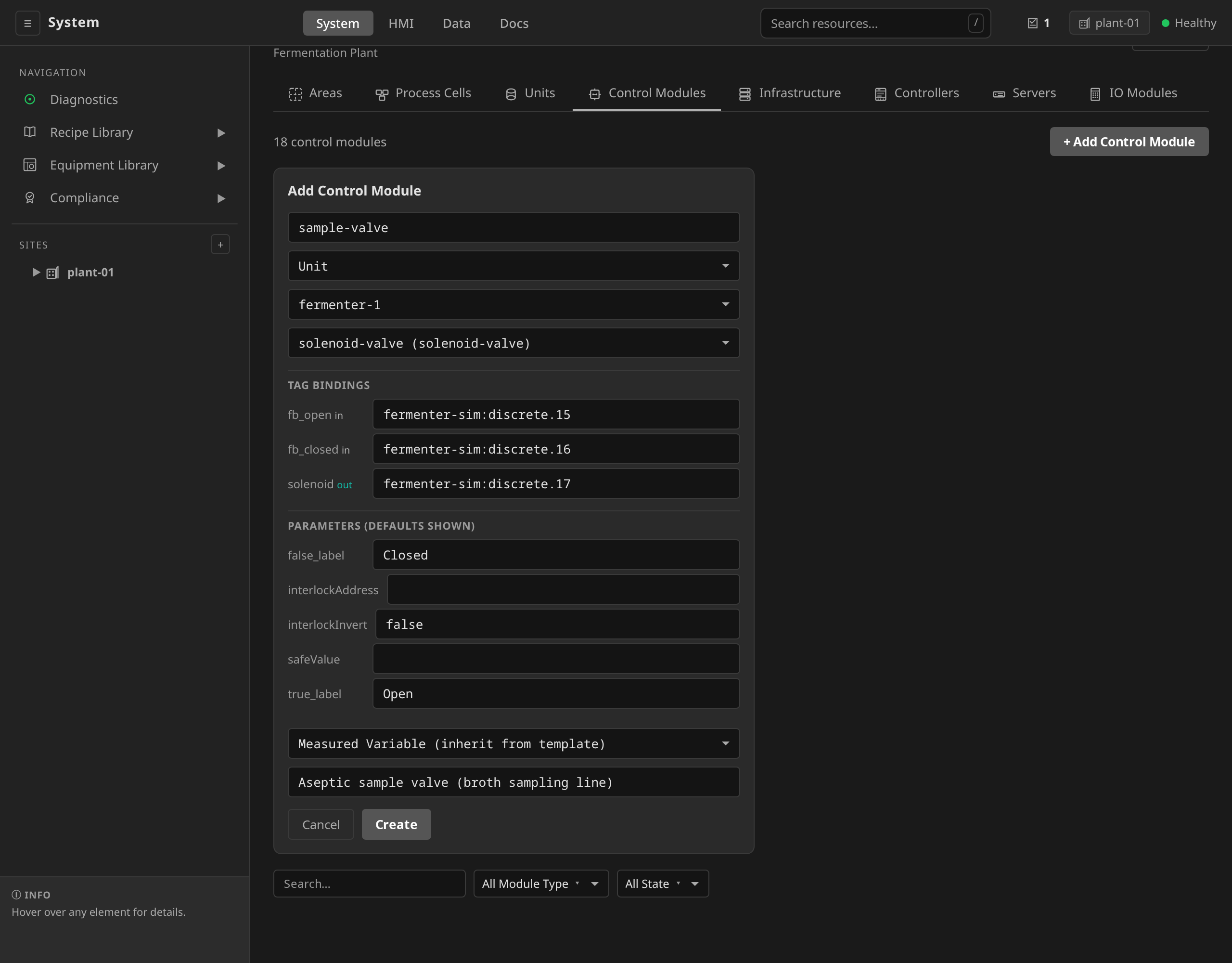
/system → expand the site → click the ControlModule
(mt1-outlet-valve) → Configuration → Edit. The
template's parameter list includes the three interlock parameters.
Set:
- interlockAddress:
tank-sim:discrete.1(the inlet valve's feedback address) - interlockInvert:
false(trip while the signal is true, i.e. while the inlet is open) - safeValue: (leave blank — defaults to de-energized/closed)
Save. The compiled program redeploys to the unit runtime and the interlock is live on the next scan. The ILCK tag appears on the module's faceplate ("Tripped"/"Clear").
dcs apply -f mt1-outlet-valve.yaml
apiVersion: physical.dcs.io/v1alpha1
kind: ControlModule
metadata:
  name: mt1-outlet-valve
  namespace: site-riverbend
spec:
  parentName: mix-tank-1
  parentKind: Unit
  templateRef: discrete-valve
  tagBindings:
    feedback: "tank-sim:discrete.3"
    state: "tank-sim:discrete.2"
  # Trip while the inlet valve's feedback says "open". Evaluated by the
  # outlet's DO block every scan on the edge — active in every mode,
  # with or without a running phase, and during control-plane partitions.
  parameters:
    interlockAddress: "tank-sim:discrete.1"
This exact configuration ships in
examples/riverbend/07-controlmodules.yaml. Notice what does not ship
beside it: a TagTrue: ILCK alarm. This interlock trips whenever the inlet
is open, which is every charge. A rule on the bare trip would annunciate a
protection doing its job, and with an exceptionAction it would hold the
batch that opened the inlet in the first place. See
Do not alarm a routine trip below.
What ships instead is a pair of rules, and the split between them is the whole of ADR 0054:
mt1-outlet-valve-mismatch, aTagTruecondition onMISMATCHwithexceptionAction: Hold. It catches equipment failure (a stuck valve or a broken limit switch) and holds the batch, because a batch cannot proceed through either.mt1-outlet-valve-command-blocked, aTagTruecondition onCMD_BLOCKEDwith noexceptionAction. It catches the interlock defeating a commanded open, and it annunciates without acting.
MISMATCH does not cover the refusal, and that is deliberate. It is
measured against the effective command (the value the output block
actually wrote, safe value included). While the interlock forces the
valve shut, the valve is doing exactly what it was driven to, and no fault
is reported. CMD_BLOCKED is true precisely when the interlock is forcing
the safe value and the standing command disagrees with it. The device
interlock protects, CMD_BLOCKED records the command it refused, and
MISMATCH is left to mean only that the device did not go where it was
driven.
The full lifecycle on exactly this valve pair (trip, gated time-boxed bypass, output following its command while bypassed, and the bypass expiring and re-arming on its own) runs end-to-end here:
mt1-outlet-valve: trip → gated, time-boxed bypass → auto-expiry and re-arm → the 21 CFR Part 11 record.Do not alarm a routine trip
An interlock trip is not automatically an alarm condition. Ask one
question before you write a TagTrue: ILCK rule: does normal
sequencing exercise this trip source?
| The trip source is… | Example | Alarm the bare trip? |
|---|---|---|
| Exercised by normal sequencing | Outlet valve interlocked against the inlet, where the recipe opens the inlet on every charge | No. The interlock arms on schedule. Alarming it annunciates a protection doing its job. |
| Abnormal by definition | Heater interlocked against low vessel level, where a running batch should never be at low level | Yes. A trip means something has already gone wrong, so it wants a timely operator response. |
A routine trip alarmed anyway is a nuisance alarm, the failure mode
ISA-18.2 alarm rationalization exists to prevent, and it does more damage
than noise when the rule carries an exceptionAction. The alarm fires during
a normal step, the exception action holds the batch executing that step,
the holding chart reverses the step, the trip clears, and Restart walks
straight back into it. The batch cannot get past the step that arms the
interlock.
The abnormal case is covered without a rule on the bare trip. A trip that
defeats a command shows up on CMD_BLOCKED, which is true only while
the interlock is forcing the safe value against a standing command that
disagrees with it. That is the alarm you want: it fires when the plant
tried to do something the interlock forbade, and stays silent when the
interlock is simply armed.
If you need the trip itself on the record, it is already there. ILCK is
an ordinary block output on the runtime's 200 ms publish cycle, so the
historian holds every transition.
Never give a refusal an exception action
A rule on CMD_BLOCKED carries no exceptionAction, and the reason is
sharper than the nuisance-alarm argument above.
An exception action invokes the holding chart, and the holding chart drives the unit's safe state (ADR 0008). A safe state is free to move exactly the process conditions an interlock reads, and on this valve pair it does. The riverbend holding chart closes the inlet valve, and the inlet valve's feedback is the outlet interlock's trip signal. Give the refusal an exception action and you get a closed loop:
operator commands the outlet open
   → interlock refuses it, forces the valve shut
      → refusal alarms with exceptionAction: Hold
         → batch holds, holding chart drives the safe state
            → safe state closes the INLET valve
               → inlet closed is the interlock's trip condition
                  → interlock clears
                     → the maintained command is still standing
                        → the outlet opens, ~4 s after being refused
Nobody re-authorised the open. The plant's own response to the refusal removed the condition that justified it. This was measured on the shipped fermentation example (#1482) and it is why the two rules are split.
The general shape to check in your own interlock set: an interlock whose
trip condition can be disturbed by an automatic response to that same trip.
The product guarantees it will not clear a trip on the operator's behalf.
No refusal it ships carries an exception action. It cannot guarantee that
your holding, stopping, or aborting chart leaves your trip sources
alone. When writing an interlock, ask what the unit's safe state does to
the signal the interlock reads. If the safe state touches it, either the
refusal must stay un-actioned (the default here) or the trip must be
latched upstream with an SR block so clearing the condition is not enough
to release it.
Note what this does not change: the interlock is non-latching and the command is maintained, so clearing the trip does release a standing command to the device (ADR 0007). That is ordinary DCS behaviour and it stays. What changed is that only a deliberate act gets you there.
Behavior details worth knowing
- Operator writes cannot defeat it. A tag write to the command
(e.g.
CMDon a valve) lands as a runtime output override feeding the block'sIN. The interlock is applied afterINis read, so the safe value still wins. This is precisely the manual-mode gap that phase guards cannot cover. - Bypassing it is a first-class, gated action. A device interlock can
be bypassed through a dedicated, permission-gated path
(
interlock:bypass, engineer/admin by default). It is never a quiet override of the trip source. A bypass is time-boxed: it auto-expires on the edge and re-arms the interlock on its own (and re-arms on a runtime restart), suppressing the entire trip (both the wiredILCKandinterlockAddress) for its window. It is annunciated via the block'sILCK_BYPASSEDoutput (aBYPASSEDbadge on the ControlModule faceplate, showing the time remaining until auto-expiry) and is audited with the acting user, a required reason, and the expiry on set/clear (21 CFR Part 11). Wire an AlarmDefinition toILCK_BYPASSEDas the audit companion. See ADR 0010. To bypass: ControlModule detail → Device interlocks → Bypass…, orPOST /api/v1/sites/{site}/controlmodules/{cm}/interlock/bypass. - Fail-safe on bad signal. If
interlockAddresscannot be read or reads quality-Bad, the interlock trips. Pair the IOModule withStateEquals: Fault/Offlinealarms (checklist item 3) so the cause is annunciated. - PID loops need the integrator held — and tracked. When an
AOdownstream of aPIDis forced, wire the trip signal into the PID'sTRKinput. Otherwise the integrator winds up against the uncorrectable error and bumps the output on release. Freezing alone is not enough if the process moves while forced: also wire theAO'sOUT(the value actually written) into the PID'sTRK_VALinput. The PID then back-calculates its integrator so its output tracks what the device really sees, and the loop resumes bumplessly from the real output on release. The librarypid-loopandpid-cascadetemplates wire both edges fromwrite_outalready, so this is automatic for any instance that enables the device interlock. The same back-calculation gives bumpless transfer for a Manual-modeCVoverride too, with no extra wiring. It is also what carries the loop across a failover: while theAOabove it is holding the value it read back from the plant, the loop tracks that value and resumes on it when something commands the loop back (ADR 0082). Seepid-loop's How it works. - Scope is one unit. The trip signal must be readable through the unit's own I/O. Cross-unit conditions belong to the phase and alarm layers (see ADR 0007).
CMD_BLOCKEDwill follow —MISMATCHwill not. On the library valves, a trip while the recipe commands "open" raisesCMD_BLOCKED, which is the record of the refused command. It does not raiseMISMATCH: the valve went exactly where the block drove it, and calling that a device fault is what let a refusal hold a batch (ADR 0054). A valve that fails to reach the forced safe position is a real fault and does raiseMISMATCH, interlocked or not.
Pattern 1: discrete-valve MISMATCH (boolean fault with debounce)
Every binary on/off valve in the reference plant uses the
discrete-valve control module, which
exposes a MISMATCH boolean tag. It's true whenever the position the block
drove the valve to and the field feedback (FB) disagree. During normal
operation the valve takes 500 ms to 2 s to stroke, so MISMATCH is briefly
true on every state change. An alarm rule that fires immediately on
MISMATCH = true would nuisance-trip every batch.
The driven position is CMD on an uninterlocked valve, which is every valve
that does not set interlockAddress. Where the two differ (an interlock
forcing the safe value against a contrary command), the difference belongs to
CMD_BLOCKED
(ADR 0054).
Derived state words don't alarm — their Boolean companions do
A module with a derived string STATE tag
(ADR 0018, e.g.
solenoid-valve's Fault/Open/Closed/Traveling) keeps its alarm
duty on Boolean tags computed from the same subnetwork: alarm conditions
evaluate Boolean/numeric tags. String equality is not among them. To
annunciate an alarm-worthy state, wrap the Boolean companion (e.g. the
both_limits output behind Fault, or MISMATCH itself) with an
AlarmDefinition. The state word is the operator's reading, and the
Boolean companion is the alarm source.
The wrong way
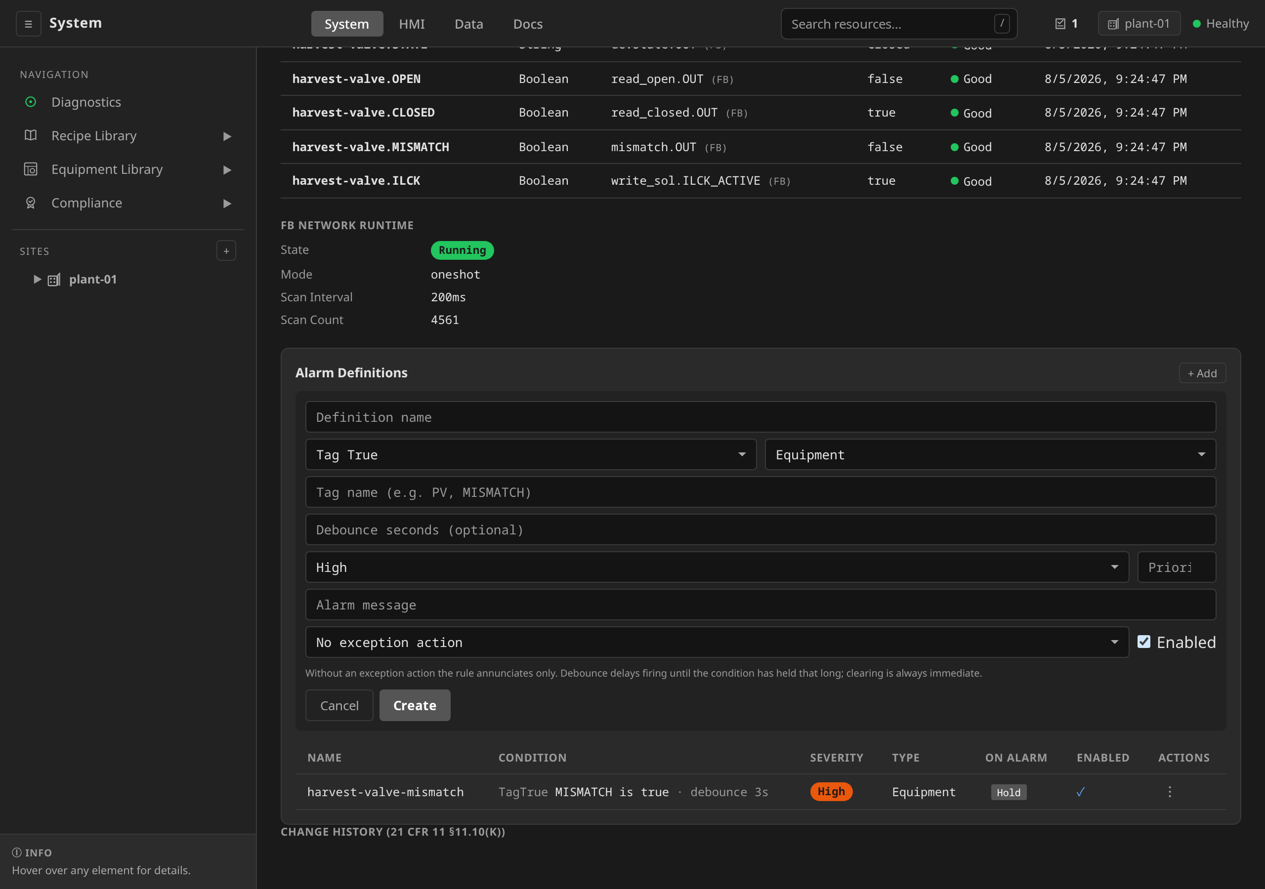
The mistake is the same in either interface: no debounce. In the UI
it's an empty/zero Debounce seconds field on the Alarm Definitions
form. In YAML it's an omitted condition.debounceSeconds. Both
produce an alarm that fires on the first scan cycle where MISMATCH
is true, which happens during every normal valve stroke.
/system → ControlModule detail (r1-wfi-valve) →
Alarm Definitions card → + Add. Fill:
- Condition type:
Tag True - Tag name:
MISMATCH - Severity:
High - Message:
WFI valve fault - Debounce seconds: (leave blank /
0) ← the mistake
Click Create → the definition is live and will nuisance-trip on the next batch. Don't actually do this on a shared cluster.
# DON'T do this — it nuisance-trips on every normal valve stroke.
apiVersion: alarm.dcs.io/v1alpha1
kind: AlarmDefinition
metadata:
  name: r1-wfi-valve-mismatch-bad
  namespace: site-riverbend
spec:
  source: { kind: ControlModule, name: r1-wfi-valve }
  condition:
    type: TagTrue
    tagName: MISMATCH
    # No debounce — fires within one reconcile cycle of the bool going true.
  type: Equipment
  severity: High
  message: "WFI valve fault"
The right way
Add condition.debounceSeconds so the alarm only fires when MISMATCH has
been continuously true for longer than the valve's normal travel time:
/system → expand the site in the left sidebar → click the
ControlModule (r1-wfi-valve in this example). Scroll to the
Alarm Definitions card → click + Add. Fill:
- Condition type:
Tag True - Tag name:
MISMATCH - Severity:
High - Message:
Reactor WFI valve CMD/FB mismatch - Debounce seconds:
3← the fix — rides through normal travel
Click Create. Each row carries Duplicate and Delete actions. There is no in-place edit. To change a rule, re-apply its YAML.
dcs apply -f r1-wfi-valve-mismatch.yaml
apiVersion: alarm.dcs.io/v1alpha1
kind: AlarmDefinition
metadata:
  name: r1-wfi-valve-mismatch
  namespace: site-riverbend
  labels:
    alarm.dcs.io/source-kind: ControlModule
    alarm.dcs.io/source-name: r1-wfi-valve
spec:
  source:
    kind: ControlModule
    name: r1-wfi-valve
  condition:
    type: TagTrue
    tagName: MISMATCH
    debounceSeconds: 3      # ride through normal travel
  type: Equipment
  severity: High
  message: "Reactor WFI valve CMD/FB mismatch — suspected stuck valve or feedback fault"
  priority: 2
  exceptionAction: Hold     # auto-pause any running batch using this unit
Key points:
type: TagTrue— fires when the boolean tag becomes logically true. Boolean tags are stored as floats in the runtime tag store, and the controller treatsvalue >= 0.5as true to tolerate numerical noise.debounceSeconds: 3— the alarm only fires afterMISMATCHhas been continuously observedtruefor 3 seconds. Three seconds covers a typical pneumatic stroke (500 ms to 2 s) plus a safety margin. For slow valves, raise to 5–10 s. For real hardware, measure your valve's travel time first.- Debounce is one-sided — clearing is always immediate. If the valve unsticks itself the alarm clears on the next reconcile cycle without waiting another 3 seconds.
- Reset on transient clear — if
MISMATCHflickers true → false → true, the debounce window resets each time it goes false. Only an uninterrupted 3-second run oftruetriggers the alarm. exceptionAction: Hold— when the alarm fires, the controller looks up every running batch whose allocated units includer1-wfi-valve's parent unit (reactor-1) and issues an ISA-88Holdcommand to each of their procedures. The batch pauses. The operator investigates, and issuesRestartfrom the HMI when the underlying problem is resolved. The rule'sExceptionActionIssuedstatus condition reports whether the command actually reached a procedure. See Alarm Management → Confirm an exception action reached the batch.
You'll find this pattern wired up for every discrete valve in
examples/riverbend/25-alarms.yaml, shipped with the product source.
It carries one MISMATCH alarm per binary valve in the reference plant.
Tuning debounce for real equipment
Cheap nuisance-trip workaround: bump debounce from 3 s to 30 s. Don't.
Instead:
- Open the trend chart on the valve's
CMDandFBtags during a normal recipe run. - Measure the longest
CMD/FBdivergence you see during a clean stroke. - Set
debounceSecondsto 2× that worst-case (so a marginal stroke doesn't trip but a true fault still does).
Typical values:
| Valve type | Debounce |
|---|---|
| Solenoid (electric, fast) | 1 – 2 s |
| Pneumatic on/off | 3 – 5 s |
| Pneumatic globe with positioner | 5 – 10 s |
| Manual handwheel-actuated motorized | 10 – 30 s |
Pattern 2: analog deviation with deadband + debounce
Deviation alarms are subtler than threshold alarms. A flow controller will
always deviate briefly during a setpoint change, when the upstream supply
hiccups, or when the operator manually adjusts the valve in Manual mode. A
naive TagDeviation rule alarms on every recipe step transition.
You need both kinds of hysteresis:
deadband— value-based hysteresis. Once the alarm is active, the deviation has to drop below(threshold - deadband)to clear. Prevents oscillation chatter at the boundary.debounceSeconds— time-based hysteresis. The deviation has to persist for this many seconds before activating. Filters transient spikes and setpoint-change recovery time.
Same flow as Pattern 1: navigate to the analog ControlModule in the
sidebar → Alarm Definitions card → + Add → pick
Tag Deviation for the condition type. The form takes the tag name,
threshold, deadband, and debounce-seconds inline.
dcs --site newark-plant apply -f flow-deviation.yaml
apiVersion: alarm.dcs.io/v1alpha1
kind: AlarmDefinition
metadata:
  name: flow-deviation
  namespace: site-newark-plant
  labels:
    alarm.dcs.io/source-kind: ControlModule
    alarm.dcs.io/source-name: flow-meter
spec:
  source:
    kind: ControlModule
    name: flow-meter
  condition:
    type: TagDeviation
    tagName: PV
    threshold: "5.0"        # alarm when |PV - SP| > 5 L/min
    setpoint: "50.0"        # nominal setpoint; can also be the SP tag's current value if you maintain it externally
    deadband: "1.0"         # only clear when |PV - SP| <= 4 L/min
    debounceSeconds: 10     # ignore transients shorter than 10s
  type: Equipment
  severity: Medium
  message: "Flow rate deviation exceeds tolerance"
  priority: 3
For temperature-control loops on a reactor or filter-dryer jacket, 30–60 s is more typical because thermal lag dwarfs flow lag.
When to use TagHigh vs TagDeviation
Use TagHigh / TagLow when... |
Use TagDeviation when... |
|---|---|
| You're alarming on an absolute hardware limit (overpressure, overtemperature) | You're alarming on a controller failing to track its setpoint |
| The threshold doesn't depend on the current setpoint | The threshold is "X away from wherever I'm trying to be" |
| The recipe might intentionally drive the PV outside a fixed band | The PV should always stay near the controller's setpoint |
| Catching hardware faults | Catching tuning, supply, or instrument problems |
Neither one tells you the instrument died
A deviation alarm on a PID loop will usually fire when the process variable's transmitter fails, because a dead 4-20 mA input reads at the bottom of span and the deviation from setpoint goes large. It tells you the wrong thing. It reports a controller that is not tracking, at the moment the loop has already driven its valve towards a rail trying to correct a reading that was never real. It also stays silent in the one case where the dead reading happens to sit near the setpoint.
The input block answers this directly. It publishes a reading only if it
stands behind it. When the driver reports bad quality, or the raw value
falls outside a configured fail band, it holds the process variable at its
last trusted value and raises a PV_BAD tag. A digital input does the
same on quality alone, so the same pattern covers a limit switch or a
position contact whose wire can break (#1998). The pid-loop and
pid-cascade templates declare that tag with role: alarm and wire it
into the controller. The controller then holds its output where it would
otherwise have wound it up.
Put a TagTrue AlarmDefinition on PV_BAD for any loop whose instrument
can fail, using the same form as Pattern 1. It fires on the first bad
scan. It names the instrument, and it is the only one of the three that
distinguishes a dead transmitter from a process genuinely at zero. Keep the deviation alarm as well, because it
covers the tuning and supply problems this one does not. The reasoning
and the limits of the fail band are in
ADR 0074.
A common mistake is using TagDeviation for both. Reserve it for "is my
controller doing its job". Use TagHigh/TagLow for safety limits.
examples/riverbend/25-alarms.yaml
shows the absolute-limit pattern. TagHighHigh on reactor temperature with
threshold 150 °C is a hardware overtemperature alarm. Tuning deviations
are TagDeviation's job.
Pattern 3: phase-level guard + parallel alarm
Patterns 1 and 2 cover post-hoc alarming. The condition occurs, then the alarm fires, then the batch is paused. For genuinely safety-critical conditions you also want a proactive guard in the phase itself: a transition that immediately moves the SFC into a held state on the unsafe condition, regardless of where the phase happens to be in its sequence, and that executes the sequence of safe actions in the right order.
Wire all the layers. The device interlock (Pattern 0) provides the always-on stop at the output. The phase guard provides the ordered procedural response. The alarm provides the audit-traceable, operator-visible record.
Phase-level guard
In a phase template's SFC, every step that drives equipment can include a
guarded transition to a safe-hold step. Example from a heat-and-react
phase.
Open the phase template in /system → Equipment Library
→ Phases → the template's detail → Edit SFC.
Declare the trip threshold first, in the toolbar's Parameters
panel, as a REAL named maxPressure. A chart that names a
variable it has not declared is refused as a whole document, with
variable maxPressure used before assignment. The declaration has
to come before the condition that reads it. Then add a safe-hold
step whose action writes the safe-state outputs (vent open, jacket
and agitator off). From each equipment-driving step, draw a
second transition to safe-hold, select it, and in the transition
inspector set its Condition ST to the trip expression
(READ('pressure_sensor.PV') > maxPressure) and tick
Interlock guard.
Ticking the box moves Priority to -1 if it is still at the
default, because that is what the admission webhook requires: an
interlock transition must carry a trip condition and a negative
priority, so it evaluates before the normal flow transitions. Save
a guard that breaks either rule and the webhook rejects the whole
template with the reason.
The transition inspector offers Interlock guard on a phase chart and on no other. A guard writes the unit's own control-module tags, which is equipment control. A step on an operation, unit-procedure or recipe-procedure chart names a child procedural element, and it drives nothing itself (ADR 0069). A procedure that needs a guard gets it from the phase template its step names.
kubectl apply is refused there too. An admission webhook rejects
transitions[].interlock on OperationTemplate,
UnitProcedureTemplate and ProcedureTemplate, on create and on
update, and names the transition to delete. Above the phase the flag
stored and armed nothing, while the change-control diff rendered it
as a structural change for an approver to sign. A guard already on
one of those documents is cleared by the next save from the editor.
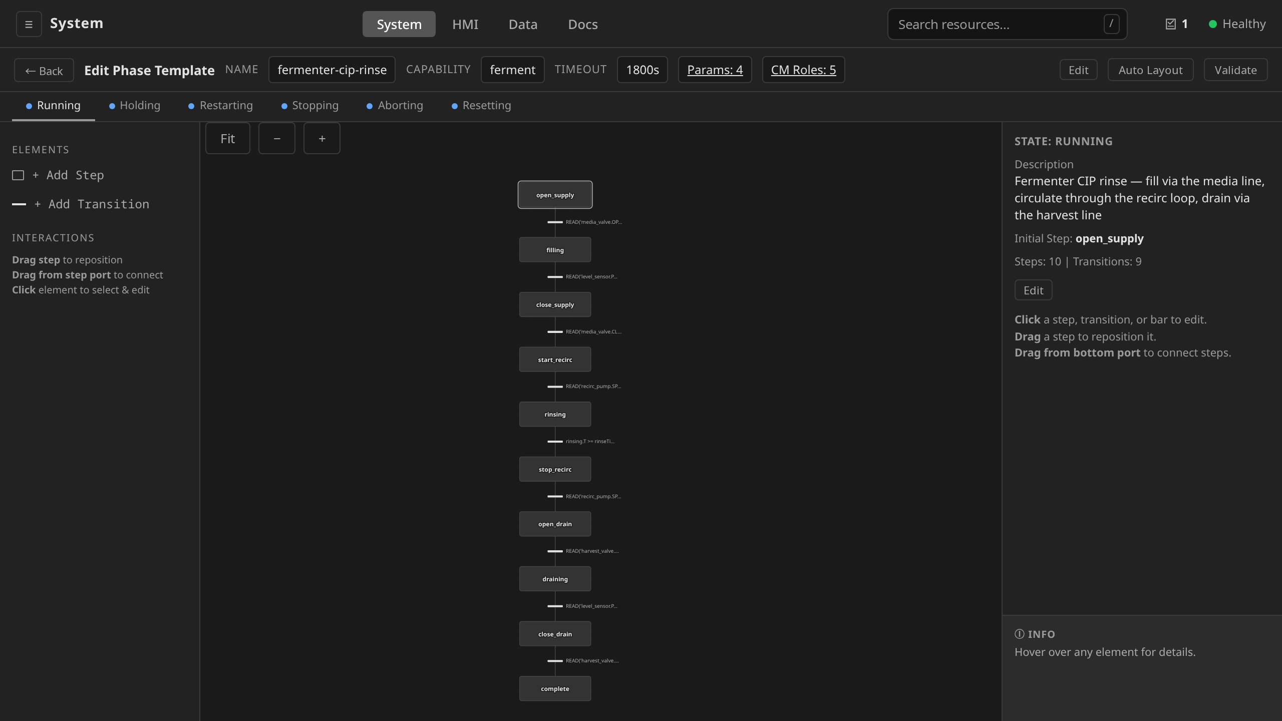
-1 because the webhook requires it. The save then runs into ISA-88's acting-state requirement. The editor's offer to seed safe-state placeholders is accepted, the template is created, and the finished guard is read back with its trip condition still there.
spec:
  parameters:
    - { name: maxPressure, type: REAL, unit: bar, defaultValue: "2.5" }
    # ... other parameters ...
  chart:
    initialStep: heat
    steps:
      - name: heat
        actionST: |
          WRITE('jacket.SP', target_temp);
          WRITE('jacket.MODE', 'AUTO');
      - name: react
        actionST: |
          WRITE('agitator.SP', agitate_speed);
      - name: safe-hold
        # Reached only via the over-pressure guard. Vent before holding.
        actionST: |
          WRITE('jacket.SP', 0);
          WRITE('agitator.SP', 0);
          WRITE('vent_valve.CMD', TRUE);
      - name: done
    transitions:
      - fromStep: heat
        toStep: react
        conditionST: "READ('temp_sensor.PV') >= target_temp"
      - fromStep: react
        toStep: done
        conditionST: "react.T >= hold_time"
      # Over-pressure guard — applies to BOTH heat and react steps.
      # Activates immediately when the trip threshold is crossed. The SFC
      # engine evaluates transitions from lowest Priority to highest each
      # scan and picks the first enabled one; a negative priority makes
      # this guard evaluate before the normal flow transitions (which
      # default to Priority 0).
      #
      # `interlock: true` marks the transition as a BPCS interlock guard.
      # The PhaseTemplate validating webhook rejects the template at admission
      # time unless every interlock=true transition carries a non-empty
      # conditionST and priority <= -1 — so a missing trip expression or a
      # forgotten priority bump is caught before the template is referenced
      # by a running batch (issue #349).
      - fromStep: heat
        toStep: safe-hold
        conditionST: "READ('pressure_sensor.PV') > maxPressure"
        priority: -1
        interlock: true
      - fromStep: react
        toStep: safe-hold
        conditionST: "READ('pressure_sensor.PV') > maxPressure"
        priority: -1
        interlock: true
What the phase guard adds on top of the device layer, and what it doesn't:
- Sequenced, multi-output response. The phase knows the order of
the safe actions (open the vent first, then cut heat and agitation)
and parks the procedure in a resumable
safe-holdstep. A device interlock can only force individual outputs to static safe values. It cannot sequence, and it does not interact with the procedure state. - Faster than the alarm path. The SFC re-evaluates transitions every scan, versus the 10-second poll (plus debounce) of a tag-based AlarmDefinition.
- Not the interlock itself. The SFC engine runs in the procedural operator on the control plane and only while the phase executes, so it covers neither idle/manual operation nor a control-plane partition. Outputs whose unsafe combination is hazardous still need a Pattern 0 device interlock underneath. The guard is the procedural layer above it (ADR 0007).
- The exception action complements the guard and replaces nothing. The alarm in the next section runs in parallel, and both fire on the same physical event.
Parallel alarm CR for the audit trail
Same flow: navigate to the ControlModule for the pressure transmitter
in the sidebar → Alarm Definitions card → + Add →
pick Tag High-High for the condition type and enter the trip
threshold. The SFC guard and AlarmDefinition fire in parallel on the
same event.
dcs apply -f r1-overpressure.yaml
apiVersion: alarm.dcs.io/v1alpha1
kind: AlarmDefinition
metadata:
  name: r1-overpressure
  namespace: site-riverbend
  labels:
    alarm.dcs.io/source-kind: ControlModule
    alarm.dcs.io/source-name: r1-pressure-sensor
spec:
  source:
    kind: ControlModule
    name: r1-pressure-sensor
  condition:
    type: TagHighHigh
    tagName: PV
    threshold: "3.0"        # absolute trip — set ABOVE the phase guard's 2.5
    deadband: "0.1"
    debounceSeconds: 5      # ride through transient pressure spikes
  type: Equipment
  severity: Critical
  message: "Reactor over-pressure (>3.0 bar) — potential containment breach"
  priority: 1
  exceptionAction: Hold
Notice the alarm's threshold (3.0 bar) is higher than the phase
guard's (2.5 bar). The phase moves the SFC into safe-hold first,
proactively venting. If pressure continues to rise (meaning the safe-hold
action didn't recover), the alarm trips at the higher threshold and the
exception action holds the entire batch. The alarm becomes the
"safe-hold didn't work, escalate" signal.
The audit record from the alarm becomes the official pharma-record entry showing the over-pressure event, its severity, the time, and the operator response.
Multi-stage escalation
The AlarmDefinition exceptionAction takes a single action from
Hold/Stop/Abort. For most plants that is enough. A dedicated
multi-stage escalation kind (timed Hold → Stop → Abort policies, the
ISA-88 Clause 7.4 escalation model) shipped as the ProcessException
CRD until #863: nothing created one at runtime, so it was purged.
Re-add on customer demand. Git history has the CRD and controller.
How alarms reach the operator
flowchart TD
    Tag[ControlModule tag changes]
    Ctl["AlarmDefinition controller<br/>polls every 10 s for tag conditions,<br/>watches K8s events for state conditions"]
    Alarm[Alarm CR created]
    HMI[HMI alarm badge + Alarms view]
    Audit[Audit trail, immutable]
    Hist[Historian alarm timeline]
    Hold["exceptionAction: Hold (if set)"]
    Resolve[Controller resolves source, affected units, running batches]
    Ann["Procedure annotation<br/>dcs.io/command: Hold"]
    Pause[Procedure controller pauses execution at the next safe transition]

    Tag --> Ctl
    Ctl -->|condition met after debounce| Alarm
    Alarm --> HMI
    Alarm --> Audit
    Alarm --> Hist
    Alarm --> Hold
    Hold --> Resolve
    Resolve --> Ann
    Ann --> Pause
The alarm count increments on the HMI's top-nav alarm badge
(#alarmBadge). Clicking it opens the full Alarms view where the
operator can acknowledge each alarm. After fixing the underlying
problem the operator issues Restart to resume the held batch.
Practical checklist for a new equipment area
When you bring up a new unit, audit your protections with this checklist:
- Every output whose unsafe combination with another signal is
hazardous has a device interlock (Pattern 0): pump vs. closed
suction valve, outlet vs. inlet, heater vs. low level. Equipment
constraints belong to the equipment, permanently, whatever recipe
happens to be running. Reserve a
TagTrue: ILCKalarm for interlocks whose trip is abnormal in itself. Where normal sequencing exercises the trip source, leave the trip unalarmed and letCMD_BLOCKEDcatch the commands it defeats (see Do not alarm a routine trip). The historian records every trip either way. - Every discrete valve has a MISMATCH alarm, debounced to ride
through normal travel time, with
exceptionAction: Hold. - Every safety-critical PV has a hardware-limit alarm — not a
deviation alarm. Use
TagHighHigh/TagLowLowwith absolute thresholds set by the equipment specification. The recipe sets none of them. -
Every IOModule has fault and offline alarms —
StateEquals: FaultandStateEquals: OfflinewithexceptionAction: Hold. These are the "the device is gone and we measured it" alarms and they must hold every batch using that I/O. They also annunciate the cause when a fail-safe interlock trips on an unreadable signal.Offlinenarrowed further in #1719. Aprotocol: simulationmodule still reaches it whenever its Controller goes away, because that Controller is the module's only liveness signal. Amodbus,opcuaorethernetipmodule readsUnknownin the same circumstance: its Controller is where the io-probe pod runs, and the runtime reaches the device over the wire (ADR 0021). Keep theOfflinedefinition on every module anyway. It costs nothing on a network module and it is the correct rule for a simulated one.Do not add
exceptionAction: Holdto aStateEquals: Unknowndefinition.Unknownmeans nothing measured the device: the io-probe did not answer, or the node it runs on went away. The runtime driving the unit holds its own connection and keeps scanning (ADR 0053). Holding there would punish a Unit that had just failed over successfully onto a healthy chassis. AStateEquals: Unknownalarm without an exception action is worth having (it tells the operator the plant has lost sight of a device), and the platform raises one of its own regardless. 5. Critical analog control loops have deviation alarms —TagDeviationwith both deadband and debounce, scoped to your tuning tolerance. Don't auto-Hold these unless your process really requires it. Let the operator decide. 6. Phases that drive hazardous equipment have transition guards independent of the alarm rules. The guard sequences the procedural safe-state. The device interlock underneath provides the always-on stop. The alarm provides the audit record and the batch-level Hold.
The complete example covering all of these (with comments explaining
each choice) is examples/riverbend/25-alarms.yaml. It ships with
the product source.
Use it as a starting template for your own equipment areas.