ISA 5.1 Compliance Traceability
Standard: ANSI/ISA-5.1-2009 Scope: Provides standard symbols for P&ID (Piping and Instrumentation Diagram) documentation used in the HMI symbol library. Coverage: Low (initial symbol set covers common instrumentation symbols) Status: In Progress
Requirements Traceability
| Symbol ID | ISA 5.1 Reference | Description | Category | Status |
|---|---|---|---|---|
valve-gate |
Table 4.6.1 | Gate valve | Valves | Implemented |
valve-globe |
Table 4.6.2 | Globe valve | Valves | Implemented |
valve-ball |
Table 4.6.3 | Ball valve | Valves | Implemented |
valve-butterfly |
Table 4.6.4 | Butterfly valve | Valves | Implemented |
valve-check |
Table 4.6.5 | Check valve | Valves | Implemented |
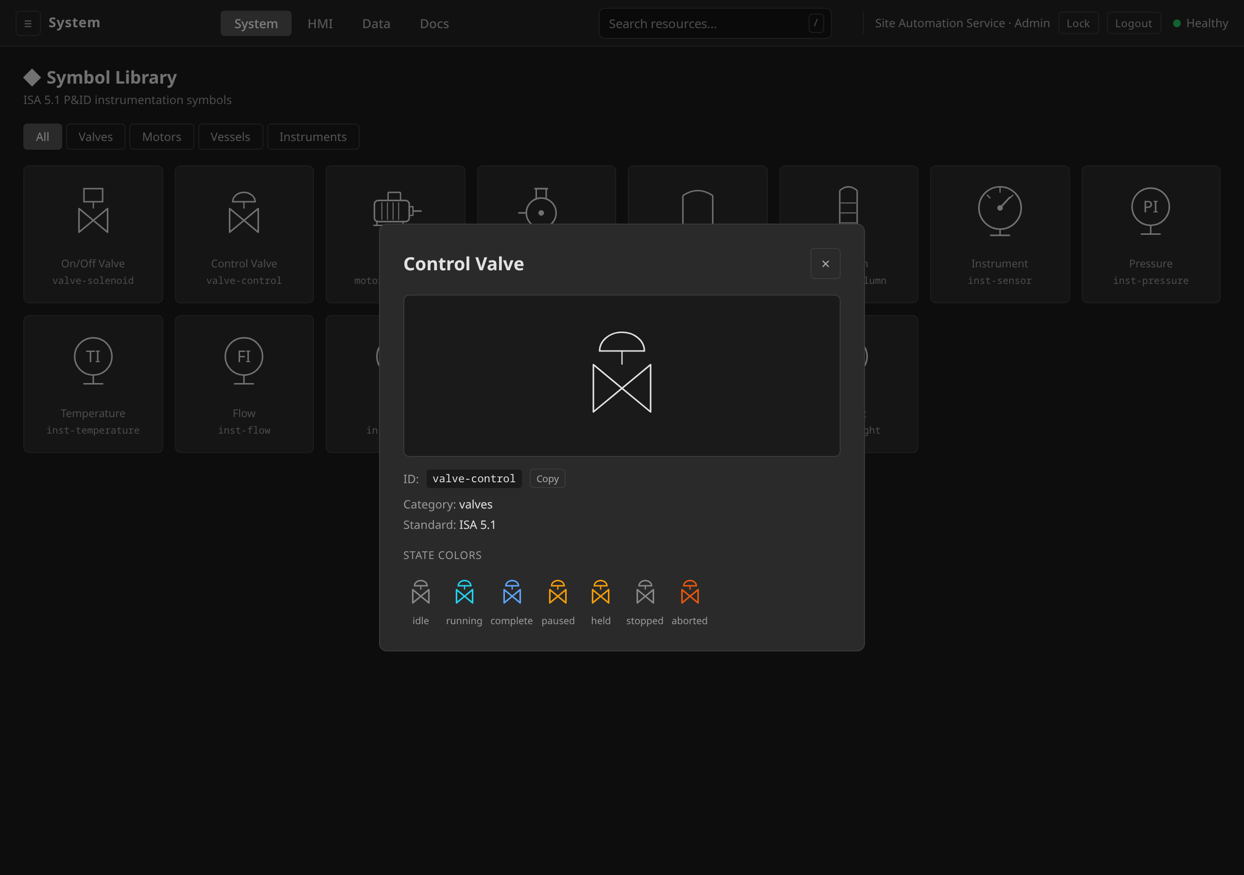
valve-control |
Table 4.6.6 | Control valve | Valves | Implemented |
valve-solenoid |
Table 4.6.7 | Solenoid valve | Valves | Implemented |
motor-electric |
Table 4.7.1 | Electric motor | Motors | Implemented |
motor-vfd |
Table 4.7.1 (var) | Variable frequency drive motor | Motors | Implemented |
motor-pump |
Table 4.7.2 | Centrifugal pump | Motors | Implemented |
vessel-tank |
Table 4.5.1 | Cylindrical storage tank | Vessels | Implemented |
vessel-reactor |
Table 4.5.2 | Reactor vessel with agitator | Vessels | Implemented |
vessel-column |
Table 4.5.3 | Distillation column | Vessels | Implemented |
inst-sensor |
Table 3.1, Cl. 5.1 | Generic instrument (gauge/dial); fallback when the measured variable is unknown | Instruments | Implemented |
inst-temperature |
Cl. 5.1 (first-letter T) | Temperature instrument balloon (tag inside circle + field stem) | Instruments | Implemented |
inst-pressure |
Cl. 5.1 (first-letter P) | Pressure instrument balloon | Instruments | Implemented |
inst-flow |
Cl. 5.1 (first-letter F) | Flow instrument balloon | Instruments | Implemented |
inst-level |
Cl. 5.1 (first-letter L) | Level instrument balloon | Instruments | Implemented |
inst-analytical |
Cl. 5.1 (first-letter A) | Analytical instrument balloon | Instruments | Implemented |
inst-speed |
Cl. 5.1 (first-letter S) | Speed instrument balloon | Instruments | Implemented |
inst-weight |
Cl. 5.1 (first-letter W) | Weight instrument balloon | Instruments | Implemented |
inst-transmitter, inst-controller, inst-indicator, inst-recorder, inst-valve-positioner |
— | Deprecated function-based aliases (#639); kept resolvable for back-compat but render the generic gauge | Instruments | Deprecated |
pipe-line |
Cl. 4.1 | Process pipe line | Piping | Implemented |
pipe-instrument-line |
Cl. 4.2 | Instrument signal line (dashed) | Piping | Implemented |
pipe-reducer |
Table 4.3.1 | Pipe reducer | Piping | Implemented |
pipe-tee |
Table 4.3.2 | Tee junction | Piping | Implemented |
Implementation
All symbols are implemented as pure SVG render functions in the HMI web UI.
Features
- State coloring: Each symbol supports ISA-88 state colors (Idle, Running, Complete, Paused, Held, Stopped, Aborted)
- Theme-aware: Symbols use
currentColorand adapt to the dark UI theme - Rotation: Optional rotation parameter for orientation variants
- Labels: Optional tag labels rendered below the symbol
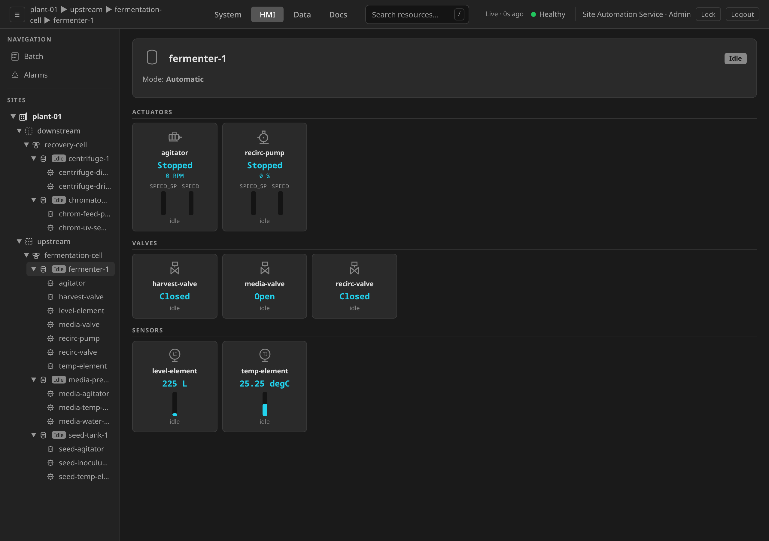
- Measured-variable instrument balloons (#639, #652): An instrument with a
known
measuredVariable(set on theControlModuleTemplate/ControlModulespec) renders as an ISA-5.1 balloon: a circle carrying the ISA tag, over an upside-down "T" field-connection stem. The first tag letter comes from the measured variable (ISA-5.1). When no variable is known the generic gauge is used, and no letter is implied. - Tag-letter shorthand (#639, #652): The derived ISA tag (e.g.
TI,PC) rides inside the balloon, with no separate badge. First letter from the measured variable, second letter from function:I(Indicate, true by construction for anything on an HMI) orC(Control, for control loops). No tag is shown when the variable is unknown. Letters are never hardcoded.
Gap Analysis
- Safety valve symbols not yet implemented
- Heat exchanger symbols not covered
- ISA-5.1 first-letter (measured variable) and the indicate/control succeeding letter are derived from real metadata (#639). The transmitter/element/recorder succeeding-letter distinction is intentionally not modeled, because it is a P&ID arrangement concern with no operator-facing meaning on an HMI
- Tag identification is not yet validated programmatically (e.g. enforcing a legal first/succeeding-letter combination)
- Shared control/display symbols (DCS, PLC bubbles) not yet included
Roadmap
- Add heat exchangers, filters, and compressor symbols
- Implement ISA 5.1 tag letter validation
- Add shared display/control symbols for DCS architecture diagrams
- Support connection point metadata for diagram wiring