Control Modules
A Control Module is a reusable Function Block network that wraps one field device (a motor, valve, or analog loop) with its interlocks, mode logic, and tag interface. Each piece of physical equipment in your plant is represented by an instance of a control module template bound to specific IOModule channels.
Control modules live one layer above I/O. The IOModule channels you authored in I/O are the raw addresses. Control modules give those channels names, scaling, alarms, and an HMI surface. Phase templates, in turn, command the field device through a control module's tags. The channel itself stays behind that interface.
One control module is one object in the plant model, however you reach it: the operator's HMI faceplate, the engineer's System detail page, and the Data records all render the same resource through the same hierarchy and the same API.
/hmi, /system, and /data.There are two CRDs to author:
| CRD | Scope | What it is |
|---|---|---|
ControlModuleTemplate |
Cluster | A reusable FB network — define once, instantiate many times. |
ControlModule |
Site | One physical device. References a template; binds template inputs/outputs to IOModule channels via tagBindings. |
In the gateway UI both live under /system → Equipment Library.
Templates are also reachable through the dcs CLI, raw YAML applied
via dcs apply -f, or directly through the REST API. All three write
to the same Kubernetes resources.
Templates
A template's logic is stored as a single IEC 61131-3 function-block
network (blocks + dataConnections). Function Block Diagram and
Structured Text are two co-equal projections of that one network.
Edit either and the other reflects, because there is only one thing
underneath (see
ADR 0012). The detail
page renders both projections, read-only, with an FBD / ST toggle in
the section header. Authoring happens in the editor (the EDIT
action), where both views are live and editable.
In the ST projection all I/O configuration is real code. Comments
carry none of it. Analog scaling and output range are named arguments on the
I/O builtins: AI('30001', rawMin := 4.0, rawMax := 20.0, engMin :=
0.0, engMax := 100.0), AO('40001', cv, outMin := 0.0, outMax :=
100.0). A device interlock compiles to an IF block. The
editable ST subset is the dataflow subset that both views can
express (read inputs → run them through function blocks → write
outputs). ST that steps outside it (a bare FOR/WHILE/REPEAT/CASE
or order-dependent sequencing) is rejected at author time with a
located error. Loops and general branching live on the phase / SFC path
instead (see Structured Text).
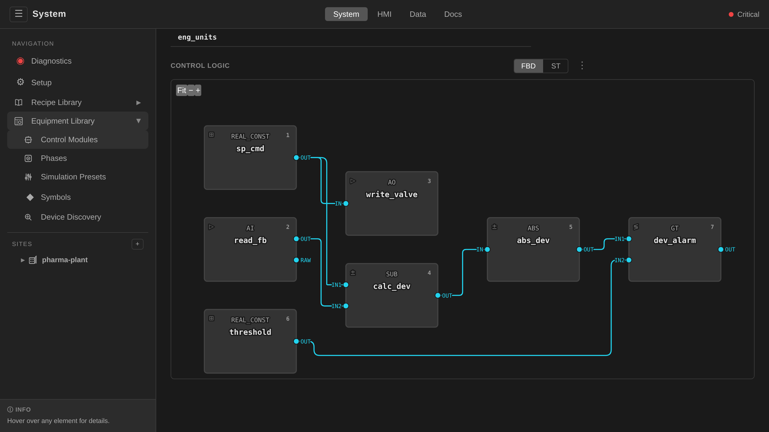
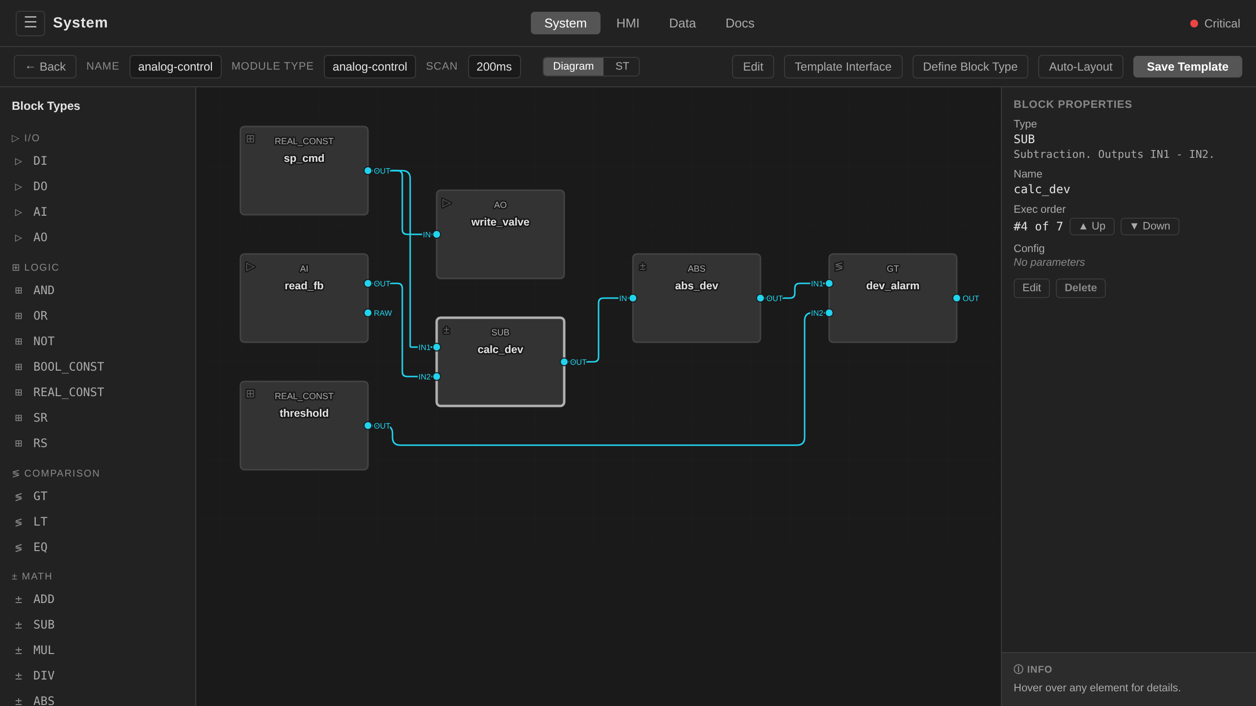
Function Block Diagram view. Blocks as labelled rectangles (DI, DO, AI, AO, AND, SUB, ABS, GT, TON, …) wired by data connections, block execution number in the top-right corner.
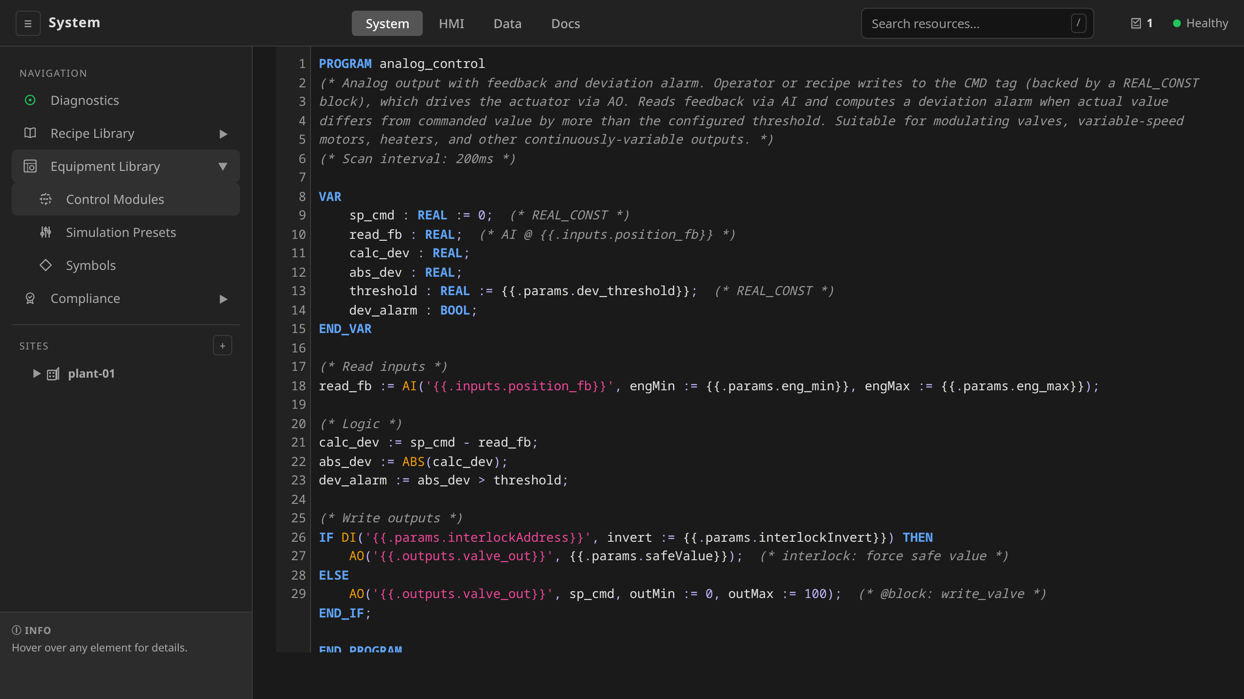
Structured Text view: the same network projected to an IEC 61131-3 program. On the detail page both projections are read-only (marked read-only). Open the editor to author logic in either form. See Structured Text for the language reference.
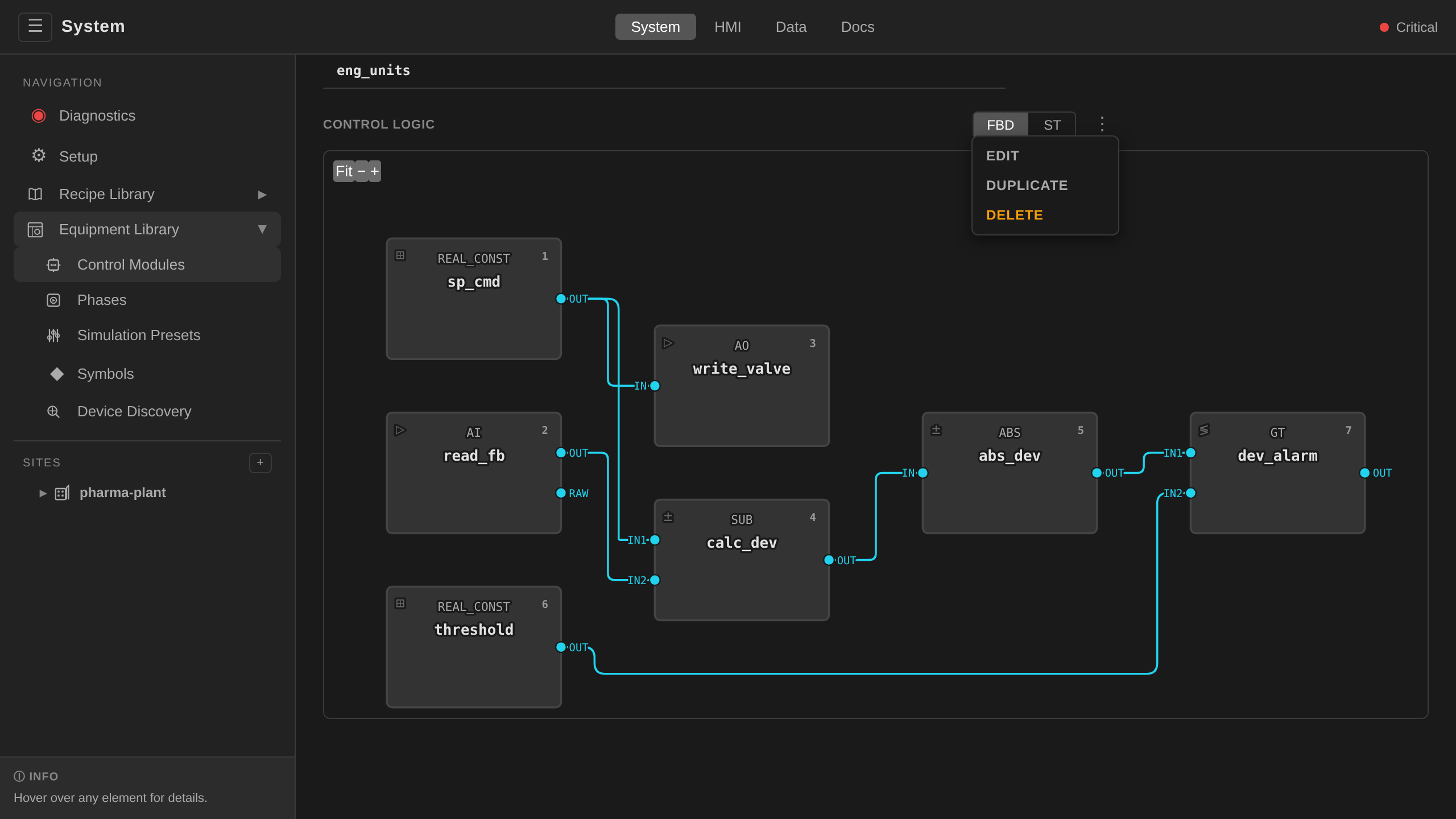
Next to the toggle, the ⋮ menu lists EDIT, DUPLICATE, and
DELETE actions for the current template.
Opening a template
/system → Equipment Library → Control Modules →
click any row. The detail page shows PROPERTIES, INPUTS, OUTPUTS,
TAGS (exposed to every instance), PARAMETERS, and the CONTROL LOGIC
section with the FBD/ST toggle.
dcs get templates analog-control            # table view
dcs get templates analog-control -o yaml    # full spec
(tpl is an alias for templates. dcs get controlmodules
fetches the deployed instances. The templates come only from
dcs get templates.)
Creating or editing a template
From the Control Modules list click + New Control Module Template
to create, or click an existing row then the ⋮ menu next to the
FBD/ST toggle → EDIT. The visual editor (route
/system#/fbeditor/{site}/template/{name}) opens. See
FB Network Editor below for the layout.
The ⋮ menu also offers DUPLICATE (fork a new template from
this one) and DELETE.
# Define the template in YAML (see example below), then apply
dcs apply -f my-valve.yaml
apiVersion: physical.dcs.io/v1alpha1
kind: ControlModuleTemplate
metadata:
  name: discrete-valve
spec:
  moduleType: discrete-valve
  scanInterval: "200ms"
  inputs:
    - name: position_fb
      dataType: Boolean
      description: Valve position feedback
  outputs:
    - name: valve_cmd
      dataType: Boolean
      description: Valve output drive
  tags:
    - name: CMD
      dataType: Boolean
      accessLevel: readwrite
      blockRef: cmd_const
      portRef: OUT
      description: Valve open/close command
  network:
    blocks:
      - name: cmd_const
        type: BOOL_CONST
        params:
          value: "false"
      - name: read_fb
        type: DI
        params:
          address: "{{.inputs.position_fb}}"
      - name: drive
        type: DO
        params:
          address: "{{.outputs.valve_cmd}}"
    dataConnections:
      - sourceBlock: cmd_const
        sourcePort: OUT
        destBlock: drive
        destPort: IN
FB Network Editor
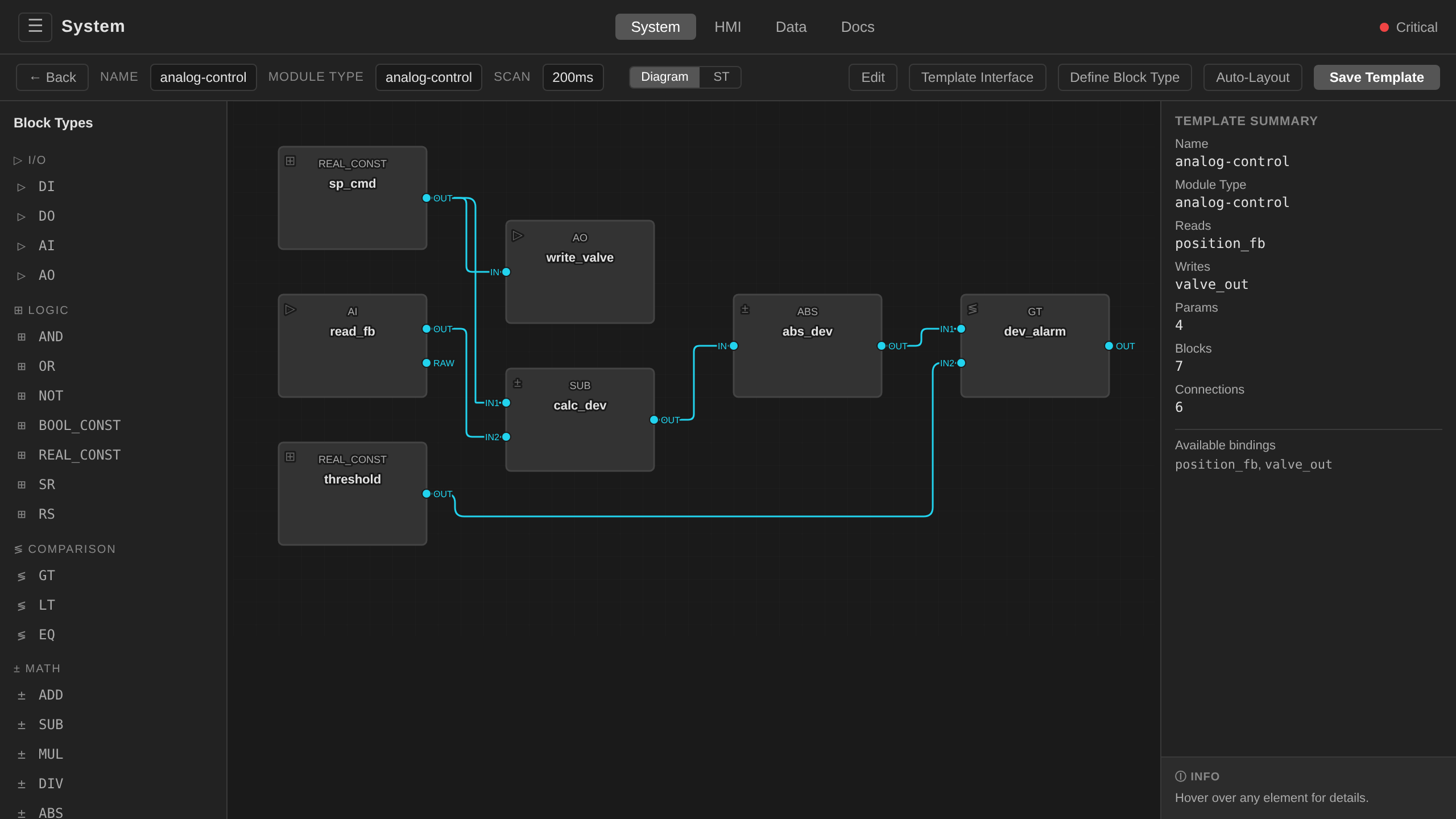
The editor has three zones and a top toolbar. All zones are resizable. Drag the divider between them.
vfd row), the whole network on the canvas at once, then toggling Diagram ↔ ST, both editable, no vendor IDE.Block Types palette (left)
Block types are grouped by category. Click a category header to expand or collapse. The categories, and the blocks that ship today, are:
| Category | Blocks |
|---|---|
| I/O | DI, DO, AI, AO |
| LOGIC | AND, OR, NOT, BOOL_CONST, REAL_CONST, SR, RS, DEVSTATE |
| COMPARISON | GT, LT, EQ |
| MATH | ADD, SUB, MUL, DIV, ABS, MAX, MIN, MOD |
| CONTROL | Timers (TON, TOF), counters (CTU), and any custom block types defined via Define Block Type |
Click a block type in the palette then click an empty spot on the canvas to place it. Click again on empty canvas to deselect.
Canvas (centre)
The working area.
- Place a block — select a palette entry, click on empty canvas.
- Move a block — drag it anywhere. Connected wires re-route automatically.
- Wire blocks — every block shows its ports as small dots on its
edges (data ports in cyan). Click an output port (e.g.
OUT), then an input port (e.g.IN1) on another block, or drag between them. The wire is stored as a connection in the template. - Fit — the canvas scales the whole network into the space it has, on open and again after Auto-Layout. No block sits off the right edge with its port labels under the panel border. It never scales up. A network that already fits is drawn at full size, which on a wide screen is every network shipped here. Drag either panel divider to give the canvas more room, and the drawing grows with it.
- Pan — drag empty canvas. A network too large for the canvas to scale into it, or one whose blocks you have dragged past its edge, scrolls under the pointer. The cursor turns into a grabbing hand for the duration.
- Select — click a block or wire. Selected elements are highlighted and their details appear in the right panel.
- Delete — select, then press Delete or use the Delete button in the right panel.
- Auto-Layout — top toolbar button. Re-runs the layered layout on the whole network without changing the topology.
Properties panel (right)
With nothing selected, shows a Template Summary card with Name, Module Type, Reads, Writes, Params count, Blocks count, Connections count, and Available bindings.
Select a block to switch to Block Properties: Type (with a short
description of its semantics), Name, Exec order (#N of total, with
Up / Down buttons to change the block's position in the execution
schedule), Config (block-specific fields, e.g. an initial value and
optional parameter binding on REAL_CONST), Edit /
Delete buttons.
Top toolbar
- Back — leave the editor without saving.
- Chart metadata chips: NAME, MODULE TYPE, SCAN — click the Edit button and they become inputs in the toolbar itself.
-
Diagram / ST toggle — switch between the two editable views of the one network. Edits in either recompile the other through the gateway's canonical transform: ST outside the dataflow subset (loops,
CASE, free-form branching) is rejected at author time with a located error.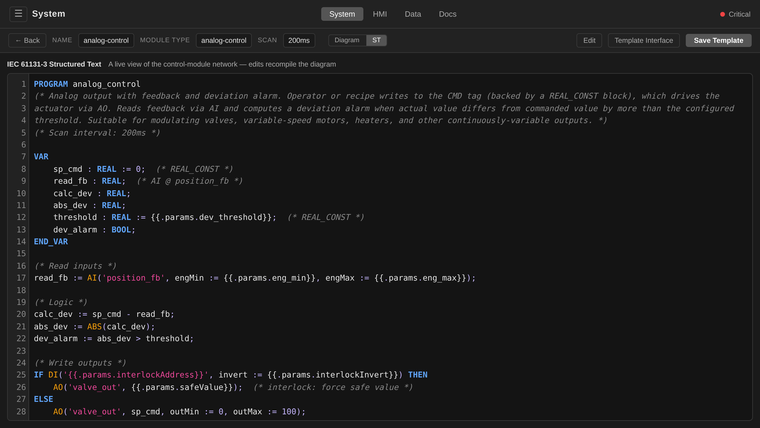 - Template Interface — expands a panel below the toolbar covering the
template's
outward-facing contract: description, Device Class (the declared
device kind that drives HMI card grouping and gauge layout:
- Template Interface — expands a panel below the toolbar covering the
template's
outward-facing contract: description, Device Class (the declared
device kind that drives HMI card grouping and gauge layout: valve,actuator,sensor,controller,other), I/O points (auto-derived from blockaddressfields), Tags (the read/write surface exposed to every instance, each with a declared role:state,setpoint,command,feedback,alarm,interlock. The role tells the HMI what the tag means, and a roleless tag renders as a generic row), Parameters (configurable values with defaults). This is where you turn a block config value into a tunable parameter via its gear icon. The diagram stays on screen below the panel, which matters because every tag names a block on it. There is no Apply step: each field takes effect as you type it, and Save Template is what writes the template. Device class and tag roles are the only source of HMI semantics (see ADR 0016: Declarative tag roles).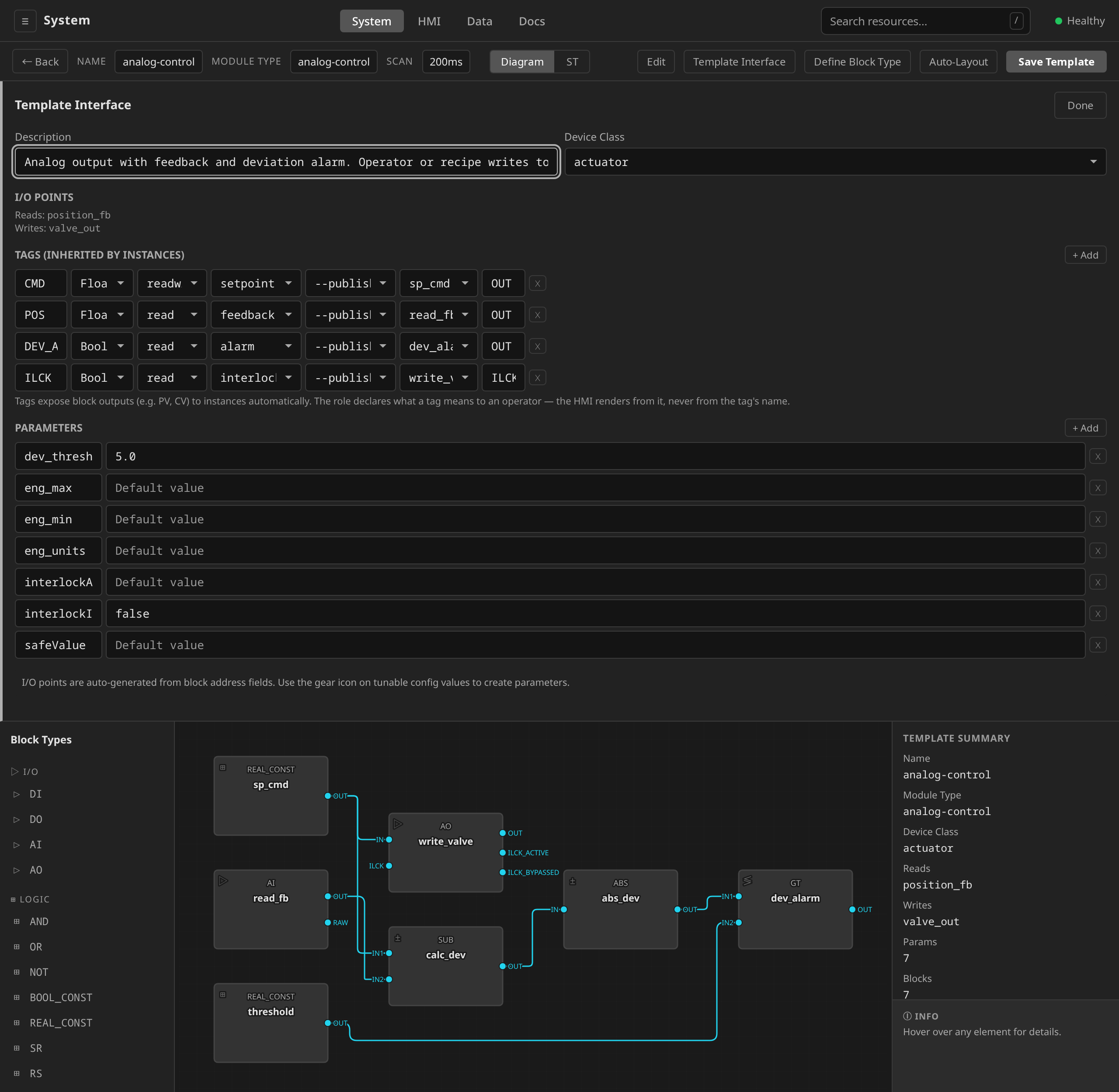 - Define Block Type — register a new function block type so it
appears in the palette. Used when adding a custom control primitive.
- Auto-Layout — re-flow the diagram.
- Save Template — commit all pending edits. Until saved, the
diagram is an unpersisted draft.
- Define Block Type — register a new function block type so it
appears in the palette. Used when adding a custom control primitive.
- Auto-Layout — re-flow the diagram.
- Save Template — commit all pending edits. Until saved, the
diagram is an unpersisted draft.
Each of these controls is offered on the signed-in session's resolved
action set as well as on the editor's state
(ADR 0024). Edit and
Save Template ask for controlmoduletemplate:update on an existing
template and controlmoduletemplate:create on a new one, Define Block
Type for functionblocktype:create, and the Diagram/ST toggle for
controllogic:transform, because both directions are a projection through
the gateway's converter. A deployment policy that denies one of those
actions removes exactly that control. The diagram, the Template Interface
panel and Auto-Layout stay, because reading a template is not one of
them.
An Info panel below the right-hand properties shows contextual help as you hover over palette items, canvas elements, ports, and toolbar controls. The same help system is used in the SFC editor.
Instances and tag bindings
A ControlModule instance points at a ControlModuleTemplate
(templateRef) and binds the template's named inputs/outputs to
IOModule channels via tagBindings. The binding string format is
<iomodule-name>:<channel-address>.
The prefix is what routes the address, so it is not optional. The unit
runtime splits a binding on its first colon and looks the prefix up
among the IOModule drivers it loaded for this unit. A binding with no
prefix is served by the runtime's own default driver instead, which is
an unconfigured simulation driver. That driver answers an address it
has never heard of at quality Bad, and the reason names it as one the
module does not carry. The tag then reads -- for the life of the
plant. The gateway refuses to save a ControlModule carrying one.
The stricter rule is that the address is a channel the named module
declares, and it is checked in a tree of documents. No cluster is
involved. Run dcs lint bindings <dir> over the directory holding your
manifests, or dcs lint <dir> to run that check together with the two
that read function block networks and template pairings. It needs no
cluster and no gateway, so it belongs in a GitOps repository's CI on a
pull request. make lint-example-bindings is the same check pointed at
this repository's own examples/.
A template-free instance whose tags carry raw addresses is the one
place a binding has no prefix, because those tags name their module in
ioModuleRef instead. The two roads meet in the runtime: the tag map
rejoins ioModuleRef and the address with a colon before either
reaches a driver.
Each unit in your plant gets one ControlModule per physical device: one for each valve, sensor, motor, PID loop. Parameters declared on the template can be overridden per instance for things like deviation thresholds, engineering ranges, or scan rates.
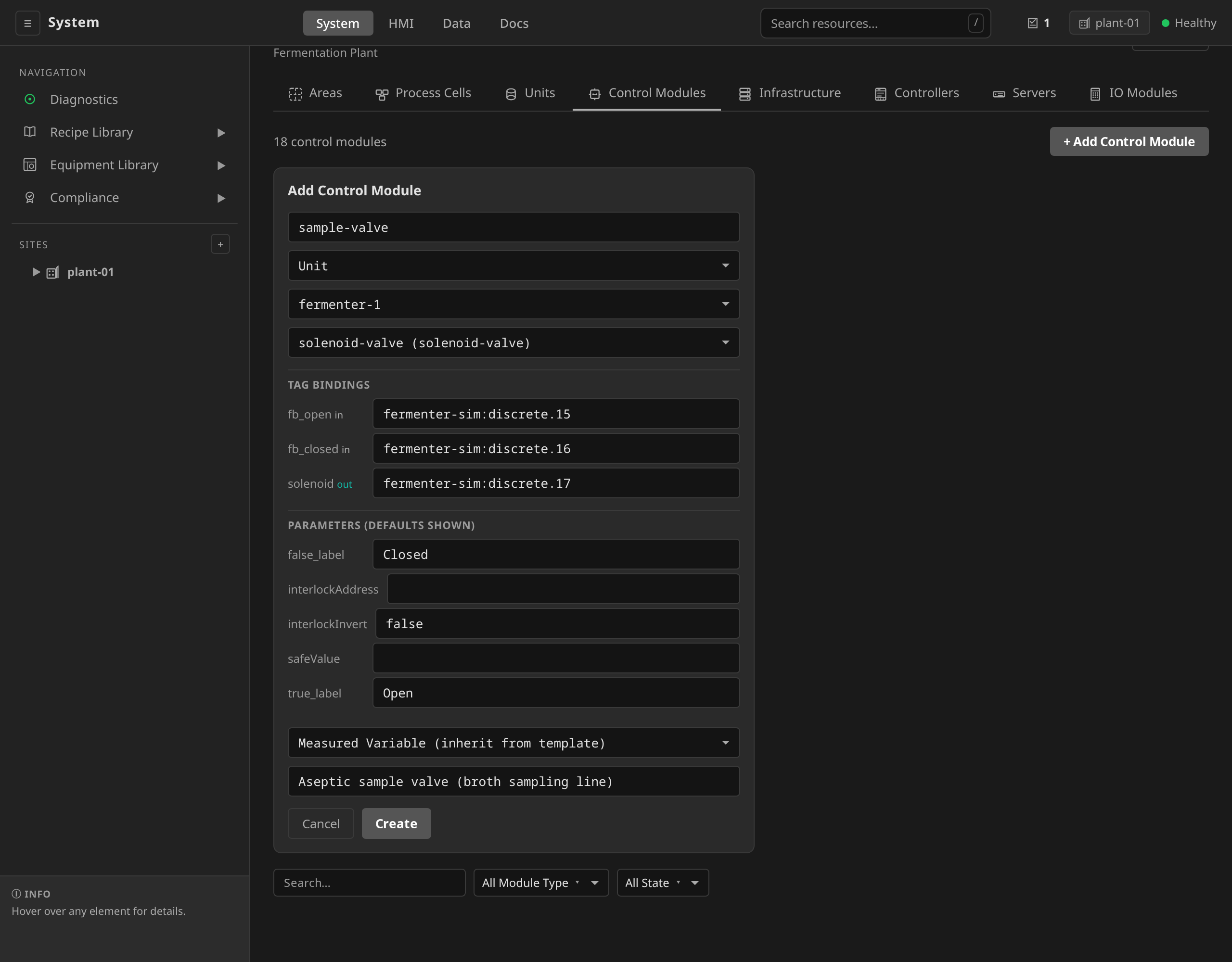
/system → Site (left sidebar) → Control Modules
sub-tab → + Add Control Module. Fill in name, parent
kind (Unit), parent unit, and pick a template. The form
then renders a Tag Bindings row per template input/output
wired into an IOModule channel address (e.g.
fermenter-sim:discrete.15). Parameter defaults appear
below and can be overridden inline. Create.
dcs --site newark-plant apply -f controlmodule.yaml
apiVersion: physical.dcs.io/v1alpha1
kind: ControlModule
metadata:
  name: r1-wfi-valve
  namespace: site-newark-plant
spec:
  parentName: reactor-1
  parentKind: Unit
  templateRef: discrete-valve
  tagBindings:
    feedback: "reactor-di:discrete.1"
    state:    "reactor-di:discrete.0"
One address per port
A binding is refused when it points a template input and a template
output at the same address. The template's input blocks read what the
input ports name, and its output blocks write what the output ports
name. One address on both sides therefore means an input block reading
a point the module also drives. No control program is produced. The
module reports TemplateResolved=False with reason
CompilationFailed.
The refusal is worth knowing before it arrives, because the shape it
catches looks reasonable: a server that exposes one read/write point,
bound as both the command and its own feedback. What makes it wrong is
the template. A template that declares a feedback
input declares an independent one, and it raises MISMATCH when the
driven position is not confirmed by that feedback. Where the feedback
is the driven point, the alarm can never be true.
Model what the device has. Where the only point is the one being
written, the driven value is already published on the output block's
OUT port. That is the effective command the alarm logic in
solenoid-valve measures against.
make lint-example-cmtemplates asks this of every module in
examples/.
Reading back a point the module writes
A point that is genuinely both the command and its current value is the
one exception, and the template declares it. On OPC UA a node is
routinely both, and on Modbus a coil is readable and writable. The
output port carries readBack: true, and an input block in the same
template takes its address from that output port:
outputs:
  - name: state
    dataType: Boolean
    readBack: true          # this point can also be read
network:
  blocks:
    - name: write_state
      type: DO
      params:
        address: "{{.outputs.state}}"
    - name: read_state      # reads the point write_state drives
      type: DI
      params:
        address: "{{.outputs.state}}"
The instance still binds one address, and there is no second port for it
to get wrong. What the read adds is the server's own answer. The output
block's OUT is the value this runtime last wrote. A write the server
clamped, a second client writing the same node, and a write that
reported success and did not take are all invisible in it and visible in
the read. examples/opcua-poc ships this as poc-discrete-output,
where the STATE and SERVER_STATE tags are the two answers side by
side.
The declaration licenses that one thing. A binding that puts a separate input port on the address an output writes is still refused, because an input port a template declares in its own right is an independent reading. The reasoning is ADR 0066.
In the editor there is nothing to declare. Type one address name on the write block and on the read block, and the Template Interface panel lists the point under Read back.
An input declared to carry no signal
A channel the plant knows is empty is declared. It is not inferred. An
input block reading Bad holds its last trusted value, raises
PV_BAD and faults its block
(ADR 0074).
Both do: the analog since #1738, and the digital since #1998.
The program then reports Degraded and a High equipment alarm stands.
That is the right answer for an instrument that died, and for one
somebody configured and nobody wired. It is the wrong answer for a
spare channel, a calibrator port, or an instrument still on order,
where the fault is a steady state and every surface it reaches stays
saturated for as long as the channel is empty.
unconnectedInputs names the template inputs this instance expects to
carry nothing, with the reason in the plant's own words:
Open the ControlModule detail page and click Edit on the Configuration section. Every template input's address field carries a No signal tick at its end. Tick it and a Reason row opens under the address. Write why the channel is empty, in the plant's own words, and Save. The address stays editable while the input is declared, because the binding stays. The same tick is on the + Add Control Module form once a template is picked. A tick with no reason is refused.
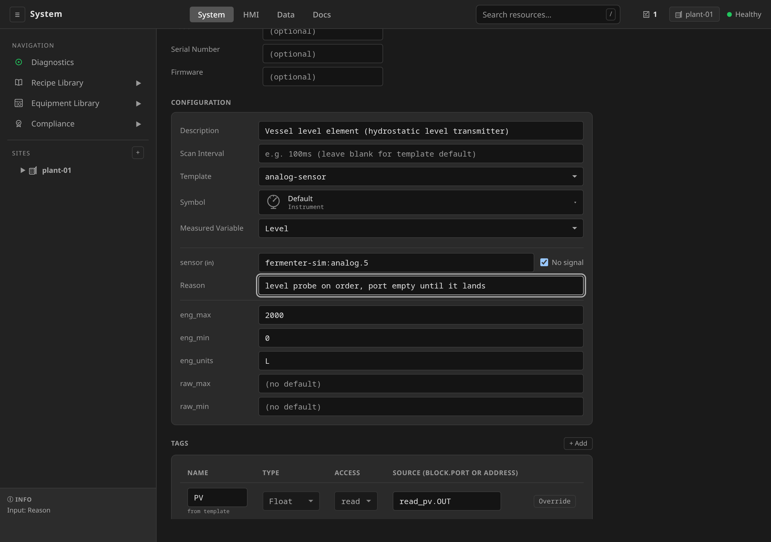
Back on the page, the binding row carries a no signal chip and
the reason under the address. The PV row in the Tags table reads
Bad with no signal declared beside it for as long as the
channel is empty, and the reason is in the qualifier's tooltip.
Untick the box and save to withdraw the declaration.
apiVersion: physical.dcs.io/v1alpha1
kind: ControlModule
metadata:
  name: cal-input
  namespace: site-bench-site
spec:
  parentName: bench-loop-01
  parentKind: Unit
  templateRef: analog-sensor
  tagBindings:
    sensor: "wago-750-352:input.1"
  unconnectedInputs:
    sensor: "loop calibrator not yet on the rack"
The binding stays, so a calibrator plugged into the port is read and
published the moment its reading arrives Good. While the channel is
empty the block still holds and still raises PV_BAD, and it does not
fault. The PV tag bound to the block's OUT is published at Bad
quality for as long as PV_BAD is raised. The HMI and the historian
therefore see an empty channel and never a held number. A read that
does not complete still faults, because the declaration is about the
channel and not about the bus.
The declaration is refused at compile time when it names a port that
is not a template input, or a port that no AI block in the template
reads. A discrete input judges no quality, and a device interlock trips
on Bad because that is the safe answer for a protection. A
declaration on a port only they read would change nothing and read as
if it had.
dcs lint cmtemplates <dir> asks the same of a tree of documents.
Which tags the instance owns
The tag table lists every tag the module has, and those tags come from two places. Most of them are the template's. They stay with the template, so an edit to the template reaches every instance that has not taken its own copy. The rest are written on the instance itself. That is how a tag is pointed at a physical I/O address, since the template's tags carry none.
The edit form marks the difference on each row. A row labelled from template is read-only, and saving the form leaves that tag with the template. Override takes a copy this module owns. The copy starts from what the template declared, including the tag's role and its engineering range, and it is editable from there. Later edits to the template no longer reach a tag the instance has overridden.
Confirming an instance is live
Once the ControlModule lands, the unit-runtime starts scanning its
function-block network. Check from the HMI faceplate. Toggle the
CMD on a valve and verify the feedback tag reacts within one scan
cycle. If the feedback doesn't move, the binding addresses are wrong
or the IOModule isn't reachable. See
Common issues in I/O.
The System detail page gives the engineering-side view of the same
liveness: with the unit-runtime scanning, the Control Logic section
overlays live block I/O values on the FB network, and the tag table
streams every declared tag with value, quality, and timestamp. A tag the
runtime declined to publish a value for, an OPC UA structure it reads no
scalar from, shows a dash for the value, Bad for the quality, and the
runtime's reason beside it
(#1943).
Alarm definitions
Each ControlModule instance carries an Alarm Definitions card on
its detail page. AlarmDefinitions are the rules that turn a tag value
or device state into an Alarm CR. They answer what should fire an
alarm and how loud should it be. Operators handle the firing alarms
themselves in the HMI. See Alarm Management for
that workflow.
The card finds its rules by spec.source. A rule belongs to the module
it names. How the rule arrived does not enter into it, so a definition
written as YAML and pushed with dcs apply lands on the same card as
one created in the form.
The same card appears on Unit and IOModule detail pages. Pick the
source whose fault you're guarding (a tag-deviation rule belongs on the
ControlModule that owns the tag, and a comm-loss rule belongs on the
IOModule). The form follows that choice: tag conditions read live values
out of the unit runtime, which only ControlModule sources have, so a
Unit or IOModule card offers StateEquals alone.
For three end-to-end worked patterns (discrete-valve MISMATCH with
debounce, analog deviation with deadband + debounce, phase-level
interlock + parallel alarm), see Alarms and Interlocks.
The full condition-type catalog (StateEquals, TagHigh, TagLow,
TagHighHigh, TagLowLow, TagDeviation, TagTrue, TagFalse) and
the armingGate / exceptionAction semantics live in the
API Reference.
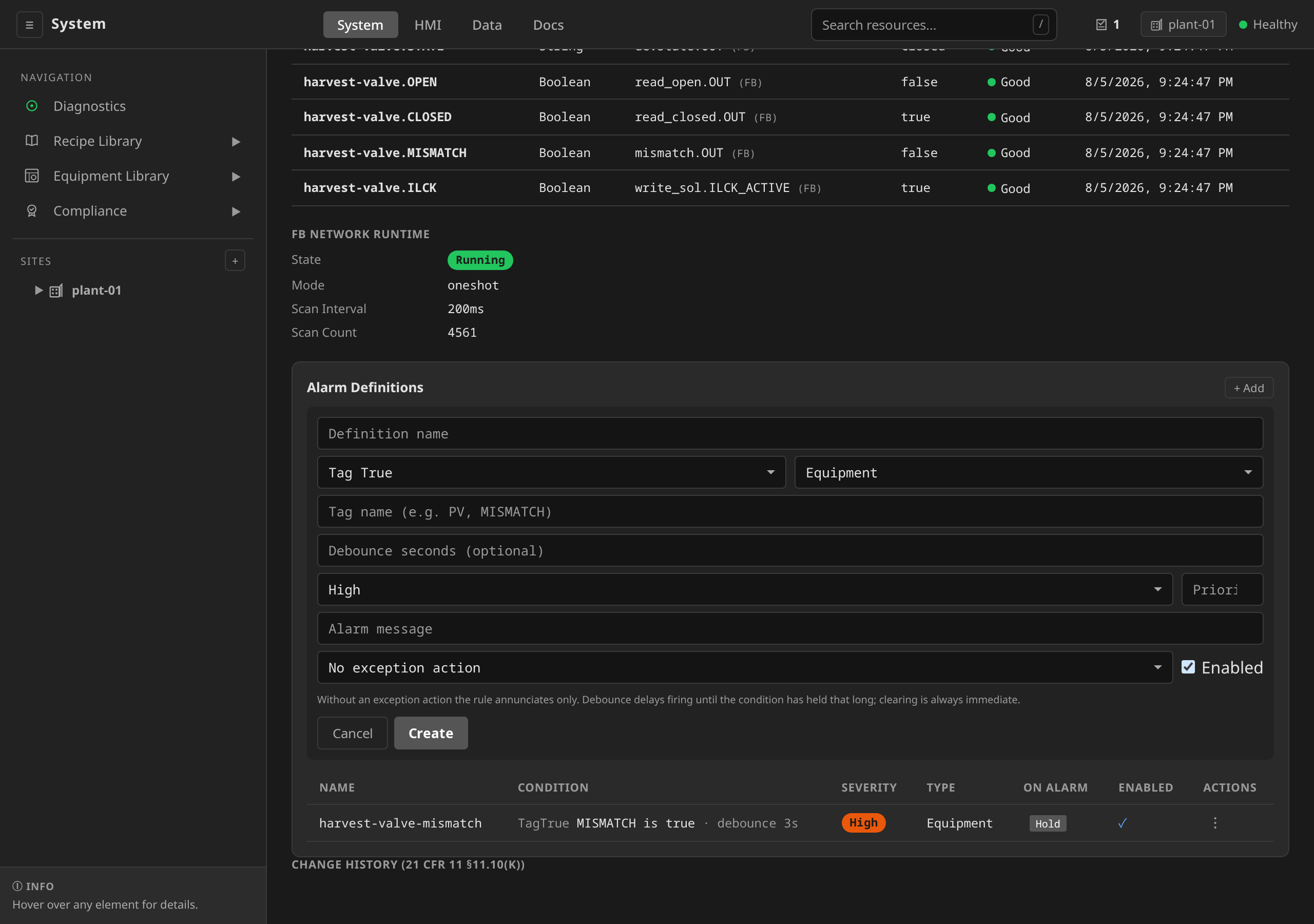
TagTrue rule with a debounce, duplicate it from the row menu, delete the copy through the Part 11 ceremony.Adding a definition
Open the ControlModule detail page and scroll to Alarm Definitions. Click + Add and pick a condition type:
Tag True/Tag Falsefor a boolean fault flag (MISMATCH,FAULT). The tag name is the whole condition.Tag High/Tag Low/Tag High-High/Tag Low-Lowfor an analog limit: tag name plus threshold, with an optional deadband.Tag Deviationfor drift from a target: tag name, threshold, and the setpoint to measure against.State Equalsto match the source's reported state (Fault,Offline). It is the only type available on Unit and IOModule cards.
The form shows exactly the fields the chosen type consumes. Fill in
severity, message, and, for anything that can flicker, debounce
seconds. The debounce is how long the condition must hold before
the alarm fires. Leave the exception action on No exception
action to annunciate only, or pick Hold / Stop / Abort to
command the batches running on affected equipment. Click Create.
apiVersion: alarm.dcs.io/v1alpha1
kind: AlarmDefinition
metadata:
  name: r1-solvent-valve-mismatch
  namespace: site-newark-plant
spec:
  source:
    kind: ControlModule
    name: r1-solvent-valve
  condition:
    type: TagTrue
    tagName: MISMATCH
    debounceSeconds: 3
  type: Equipment
  severity: High
  message: "R1 solvent valve CMD/FB mismatch"
  exceptionAction: Hold
Apply with dcs --site newark-plant apply -f r1-solvent-valve-mismatch.yaml.
Editing or deleting a definition
Each row in the Alarm Definitions table carries a row-action menu with
Duplicate (copy the spec into a new definition) and Delete.
Deleting prompts for confirmation and removes the AlarmDefinition,
and the alarm-operator garbage-collects any Alarm CRs the rule had
raised. There is no in-place edit form in the UI. To change a
definition, either delete and re-add, or fetch the YAML, edit it, and
re-apply:
dcs --site newark-plant get alarmdefinitions \
  r1-solvent-valve-mismatch -o yaml > def.yaml
# … edit def.yaml …
dcs --site newark-plant apply -f def.yaml
Disabling a definition without deleting it (spec.enabled: false)
auto-clears any active alarm it had raised. The AlarmDefinition
stays in place for future re-enable.
Symbols
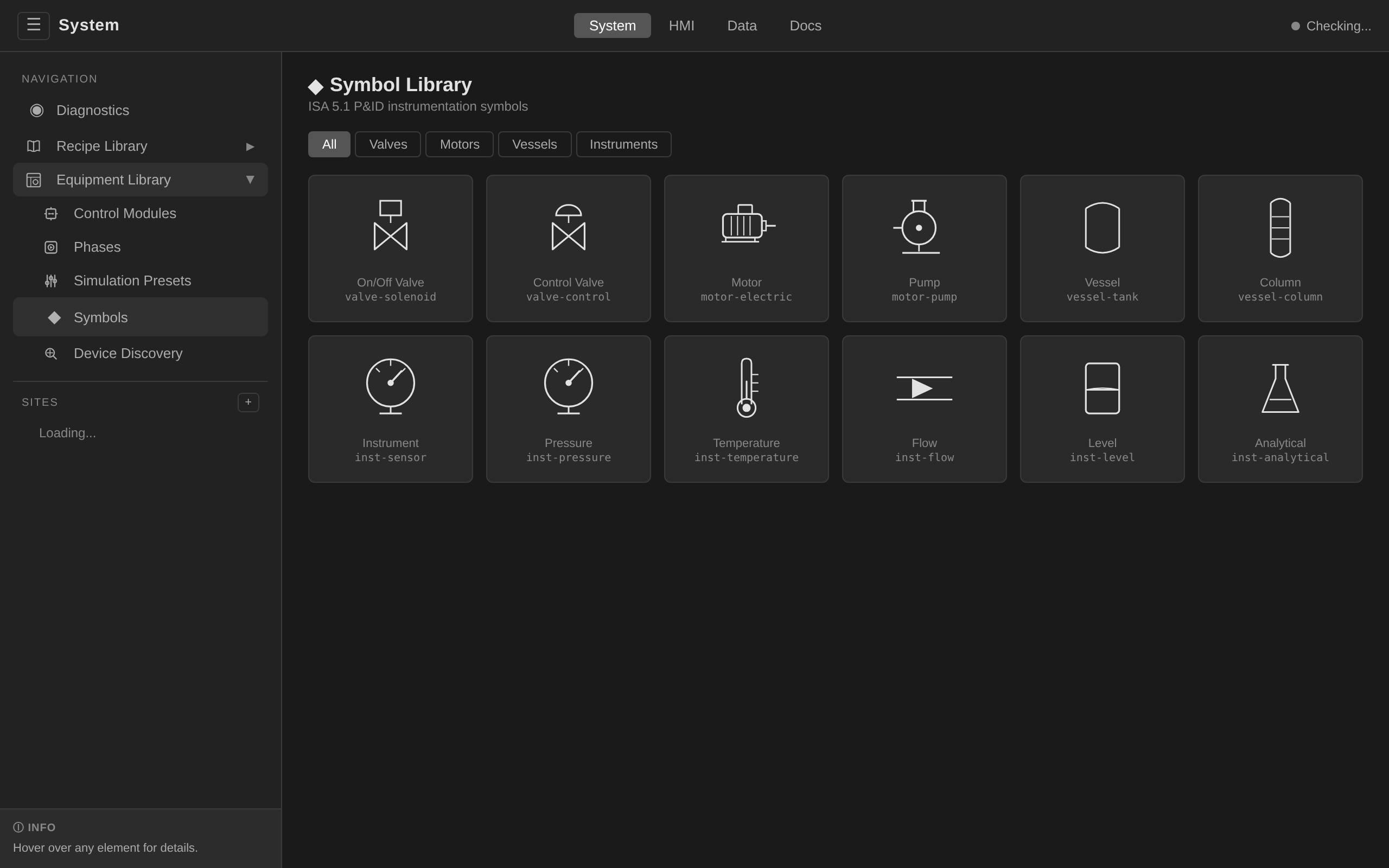
The Symbols library contains ISA 5.1 process symbols used on the HMI
process view. ControlModules reference a symbol to pick how they render
on the unit detail dashboard. The symbol library ships with the
gateway UI. Browse it at /system → Equipment Library →
Symbols and click any symbol to see its SVG preview and metadata.
Assigning a symbol
When you create or edit a Control Module, the Symbol field is a
visual picker. Click it to open a searchable gallery, grouped by
category and rendered from the live symbol registry, and pick the
glyph by sight with no motor-vfd-style ID to remember.
The picker reads the registry directly, so it always reflects the currently
shipped symbol set.
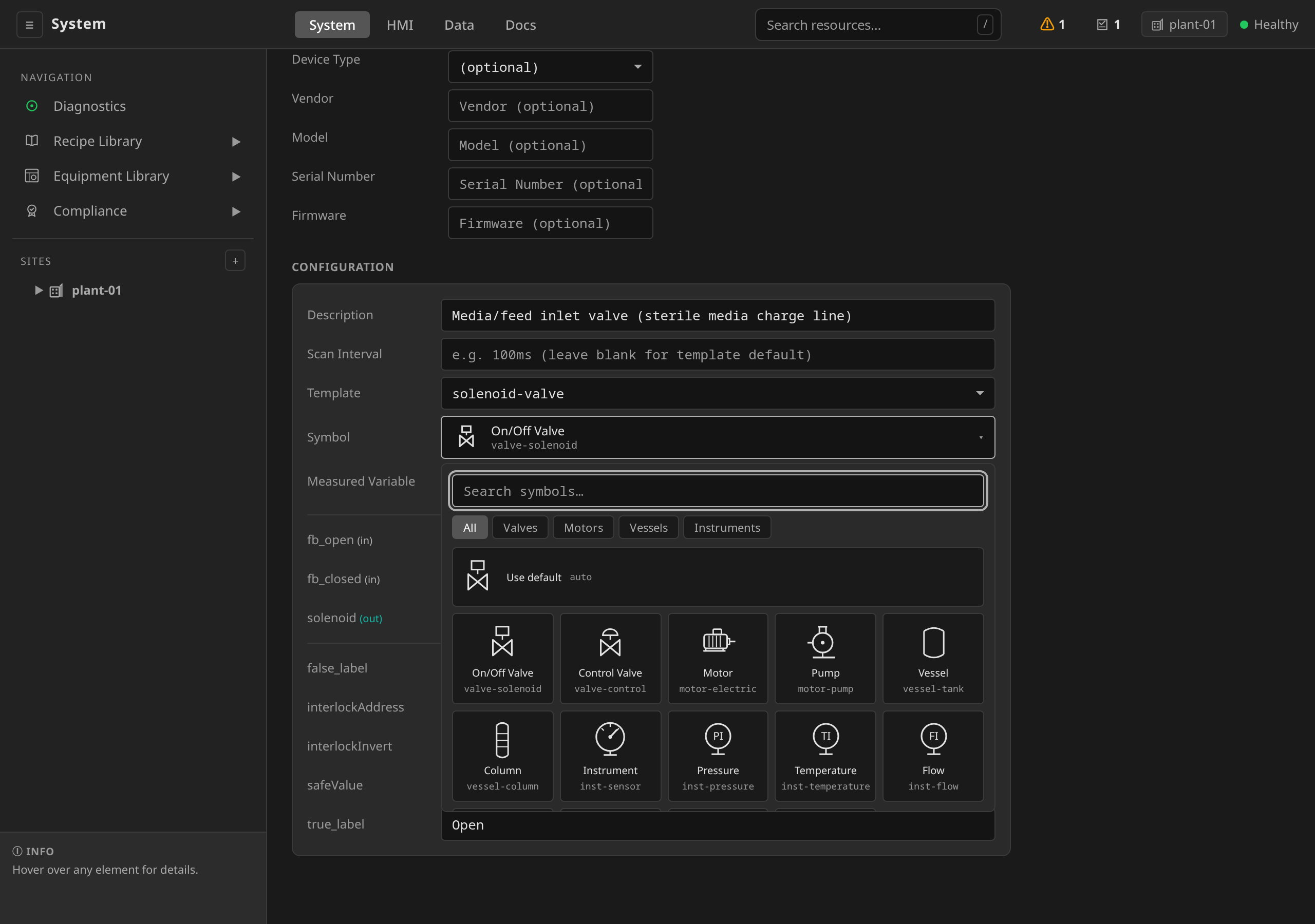
Leaving the picker on Use default stores no instance override. The glyph then resolves through the template's default symbol and finally the module type, exactly as the HMI renders it. The picker previews that effective default so you can see what you would get before overriding it.
Versioning and immutability
Control Module templates are referenced by every instance by name and version. Changing a template's logic after it has been deployed to running equipment is guarded by RBAC and captured in the audit trail. For major behaviour changes, create a new template version and leave the existing one in place. See Recipes for the full recipe-and-template change control flow.
A template that instances still reference cannot be deleted. Every ControlModule recompiles its control program from its template on each reconcile, and the cluster holds no other copy of that logic. A deleted template therefore strands each instance on the program it last produced, with no way to rebuild it. The gateway answers HTTP 409 and names the modules still using the template. Repoint or delete those instances first.
The declared model is also enforced: an out-of-band edit to a running
module's spec (a raw kubectl patch around the gateway) is detected
and reverted by the ControlModule compiler, and the correction lands in
the audit trail as a DriftCorrected record.
kubectl patch (100ms → 9999ms) auto-corrected without anyone clicking anything, and the DriftCorrected audit row is the receipt.Related Documentation
- I/O — the IOModule channels these instances bind to.
- Phases — phase templates command the field device through control-module tags.
- Library — Control Modules — the shipped templates (discrete-valve, analog-sensor, pid-loop, …).
- Structured Text — language reference for the ST view and for inline ST in custom block types.