I/O
How to author the bottom layer of the stack: the IOModule resources
that describe physical I/O hardware, and the SimulationPreset
resources that stand in for hardware on the simulator. Everything
above this layer (control modules, phases, recipes) is hardware-
agnostic. All the hardware variation lives here.
The whole point of this layering is that the phase templates, operations, unit procedures, and recipes don't change at all when you move from sim to real hardware. All the variation lives in the IOModule (or its simulation equivalent).
Integrators: see the API Reference for the REST equivalents of the actions on this page.
Protocol support and validation status
Cloud-Native DCS draws a sharp line between implemented and field-proven. A driver compiles, has unit tests, and looks plausible in a code review long before it has talked to a real PLC. We label each one explicitly so you can size the gap between "checks the box" and "trust this on a regulated batch."
Status legend
- Field-proven — exercised end-to-end against real hardware on the reference rig. Safe to deploy.
- Implemented-untested — code is in tree with unit tests and no metal proof yet. Treat as PoC-grade until validated for your device.
- Bridge — no native driver. Reach the device through an OPC UA gateway (Kepware, FactoryTalk Linx Gateway, vendor-native OPC UA server).
- Not supported — no driver, no bridge in tree.
By protocol
| Protocol | Status | Signal types proven | Reference rig | Caveats |
|---|---|---|---|---|
| Modbus TCP | Field-proven (DI/DO/AI/AO) | DI, DO, AI, AO | Wago 750-352 coupler + 750-430 DI + 750-454 AI + 750-554 AO + 750-530 DO | Analog proven end-to-end at B9 commissioning: a PID phase drove the 554→454 4-20 mA loop through a full recipe, tracking within one 12-bit LSB (seven-point sweep ±0.15 % of span; word encoding verified with non-trivial values). This lineup exchanges single 16-bit words, so metal has only ever exercised one register at a time. Wider values are supported — see 32-bit and wider values — and all four vendor layouts (ABCD, CDAB, BADC, DCBA) are proven in both directions against an independent Modbus implementation by pkg/driver/modbus/interop_test.go. No cross-register value has been read off a physical device. |
| OPC UA | Field-proven for the secured channel, read, discrete and analog write, subscribe, discovery, and the unit-runtime session from a Secret-backed IOModule (see caveats) | DI (read), DO (read/write), AI (read), AO (write); subscribe; discovery | WAGO CC100 751-9301 (native CODESYS 3.5 OPC UA server, firmware 04.09.01) on the bench OT VLAN; mcr.microsoft.com/iotedge/opc-plc and open62541 remain the CI references |
Proven on 2026-09-02 against the CC100 over Basic256Sha256 + SignAndEncrypt, username auth and an X509 client identity, server certificate pinned by SHA-256: connect, ReadValue, WriteValue (Bool), read-after-write, and a 50 ms subscription, through both pkg/opcuaclient (dcs opcua) and the gateway discovery API and wizard (#873, #922). A certificate-provisioned CC100 advertises no None endpoint, so there is no unsecured baseline on this class of controller. Trust ceremony as executed: the server certificate is pinned by fingerprint on the client side; the client certificate is filed in the controller's quarantine store on first contact and moved to its trusted store by hand, after which the runtime must be restarted (#301). The copper loop closed on 2026-09-03 with jumpers from DO1 to DI1 and AO1 to AI1: DI1 followed DO1 through the wire on both edges, the field change reached a subscription, and AI1 tracked a 0 to 10 V sweep commanded through AO1_EU to within 51 counts, 0.16 % of span (cndcs-deploy-bench scripts/plc-verify.ps1, 11 of 11). One wiring fact the controller's manual carries and the bench notes did not: the DO group on X5 is on the field level, electrically isolated from the system level the DIs sit on, so X5.2 must be landed on 0 V as well as X5.1 on 24 V or every output sources nothing while the process image reports TRUE. Four gaps the bench found, none of which the reference simulator can show: a write encoded the Go value it was handed and ignored the node DataType, so every REAL, INT and WORD write was refused (#1910, closed: both write paths now read the node's DataType attribute and encode to it, proven against open62541's typed scalars in make test-interop, and taken on the CC100 on 2026-09-03: a phase's AO block wrote 3.3 to the REAL tag AO1_EU and the controller's own scaling put 10813 on AO1_RAW); a DataType outside namespace 0 was typed from its sampled value, so a CODESYS WORD was discovered as String (#1911, closed: discovery and both write paths now walk a vendor DataType to the built-in it descends from, one inverse HasSubtype browse per type per session, proven against a node-opcua controller fixture that types its tags as the PLCopen companion does in make test-interop, and taken on the CC100 on 2026-09-03: the discovery API and the wizard both type every WORD channel UInt16 and both INT RTD channels Int16, the CLI's --type Double write to a WORD tag reaches the controller as a UInt16, and a value the type cannot hold is refused before the wire); the IOModule held its password in the CR and named certificate files nothing mounted, so the unit runtime could not open a secured session at all (#1912, closed by spec.security and the Secret projection under ADR 0087, and re-run on the CC100 on 2026-09-03 from a kind stack on the v0.7.3 release images: the unit runtime and the io-probe opened Basic256Sha256 and SignAndEncrypt with a username token from the projected Secret, the module went Online with CredentialsSecured=True, and three batches drove the run lamp and AO1 from a phase, read back from the controller by a second client); and the discovery wizard dropped the tuple it verified from the IOModule it emits (#1913, closed: it now writes the tuple onto the module, and taken on the CC100 on 2026-09-03: the emitted IOModule carried Basic256Sha256, SignAndEncrypt, username, the Secret by name and the pinned fingerprint, the step 4 panel showed all of them before Apply, and the applied CR read back with the same block). The bench also found that a scan from a root node the server does not know is reported as an empty subtree (#1934). The re-run also found that the v0.7.3 IOModule CRD does not install on a 1.31 apiserver, because its cross-namespace rule spelled credentialsRef.namespace where CEL needs __namespace__; fixed and held by make lint-crd-cel-reserved. Reproducer: examples/opcua-poc/; bench record: cndcs-deploy-bench/plc/. |
| Simulation | Field-proven | DI, DO, AI, AO | in-cluster (no hardware) | Backs the entire riverbend reference simulation and screenshot pipeline. |
Modbus TCP and EtherNet/IP are plaintext protocols
They carry no authentication and no encryption, so any host that can
reach the I/O module can read and write process I/O. Production
deployments must compensate with network segmentation: a dedicated
field-bus segment reachable only from the device nodes, scoped by
networkPolicies.fieldBusCIDRs. The required zone/conduit controls
are spelled out in the
threat model.
Where the hardware offers it, prefer OPC UA with Sign or
SignAndEncrypt, the only field protocol here with built-in
integrity protection.
Not customer-ready
The drivers below compile and have unit tests but have not been validated
against real hardware. They are disabled by default. unit-runtime refuses to
load them unless started with --enable-experimental-drivers, and the gateway
UI does not offer them in the + Add IOModule form. They remain in the tree
so a partner with the relevant hardware can opt in and validate.
| Protocol | Status | Reason it's gated | Recommended alternative |
|---|---|---|---|
| EtherNet/IP | Experimental — implemented, untested, opt-in only | Generic Device Profile only (assembly-instance addressing). No vendor device has been validated. Does not support ControlLogix / CompactLogix CIP-tag addressing, which is a different protocol layer. | Bridge Rockwell PLCs through OPC UA via FactoryTalk Linx Gateway or Kepware. Tracking: #272. |
By vendor / device family
| Vendor / family | Recommended path | Status |
|---|---|---|
| Wago 750 series | Modbus TCP (native) | Field-proven for DI/DO/AI/AO |
| WAGO CC100 / PFC (CODESYS 3.5 runtime) | OPC UA (native server on the controller) | Field-proven for the secured channel, read, discrete and analog write (#1910), subscribe, discovery, and the unit-runtime session from a Secret-backed IOModule (#1912, ADR 0087). Publishes only what a CODESYS application declares in its Symbol Configuration |
| Siemens S7-1500 / S7-1200 | OPC UA (native server on the PLC) | Untested on this family; the driver is field-proven against a CODESYS native server (row above) |
| Siemens S7-300/400, PCS 7 | OPC UA via Kepware or Siemens IDLink | Bridge, untested |
| Rockwell ControlLogix / CompactLogix | OPC UA via FactoryTalk Linx Gateway or Kepware | Bridge, untested |
| Rockwell Point I/O (1734-AENT) | OPC UA bridge (recommended) or EtherNet/IP generic | Bridge, untested; native EtherNet/IP is experimental and gated — see Not customer-ready |
| Beckhoff TwinCAT | OPC UA (native) | Bridge, untested |
| Schneider M580 / Modicon | Modbus TCP (native) | Implemented-untested for this family |
| Mitsubishi MELSEC | OPC UA via Kepware | Bridge, untested |
| Profinet devices | OPC UA via gateway | Bridge, untested |
| HART instruments | OPC UA via HART-IP gateway | Bridge, untested |
| DeviceNet, DH+, Foundation Fieldbus, Profibus PA | none in tree | Not supported |
| Direct CIP-tag addressing on ControlLogix | none in tree | Not supported (use OPC UA bridge or contribute a driver) |
If your device isn't here. This project is solo-maintained, with
paid engagements adding drivers as design partners come on board. If
your plant runs something not in the matrix, the realistic options
are: (a) front it with an OPC UA gateway you may already own
(Kepware is the industry default), or (b) contract a driver build
as part of an engagement. The pkg/driver/ interface is small
(Connect, ReadValue, WriteValue, Subscribe). A driver added
under engagement is delivered to the customer under the same license
terms as the rest of the codebase.
Sim vs real — the two layers that change
The entire hardware surface area lives in two places:
- The IOModule resource — switches from
protocol: simulationwith an inlinespec.simulationblock (or referencedSimulationPreset) toprotocol: modbus(orethernetip,opcua) with a real network address. - The ControlModule
tagBindings— these keep referring to IOModule channel names (analog.0,discrete.1, etc.). On sim those names resolved to virtual simulation slots. They now resolve to real hardware addresses. See Instances and tag bindings in Control Modules.
Everything above that (phase templates, operations, recipes, the state machine, the HMI, alarms, audit trail, batch records) is hardware-agnostic.
Authoring an IOModule
An IOModule has the same shape regardless of protocol. Only
protocol, address, the optional options block, and (for
simulation) spec.simulation differ. The example below creates a
simulated reactor IOModule as the reference plant ships it. Switch the protocol
field to modbus or opcua to drive real hardware, or ethernetip
if you've opted into experimental drivers (see Not
customer-ready). See
what changes between sim and real below for the
per-protocol differences.
/system → Site (left sidebar) → IO Modules sub-tab
→ + Add IOModule. Fill Name, pick a Controller
(the device node running the runtime), and pick a Protocol. The
address hint and protocol-specific options block update as you
change it, and selecting simulation auto-fills Address to
sim://local. Add channels in the channels table. Create.
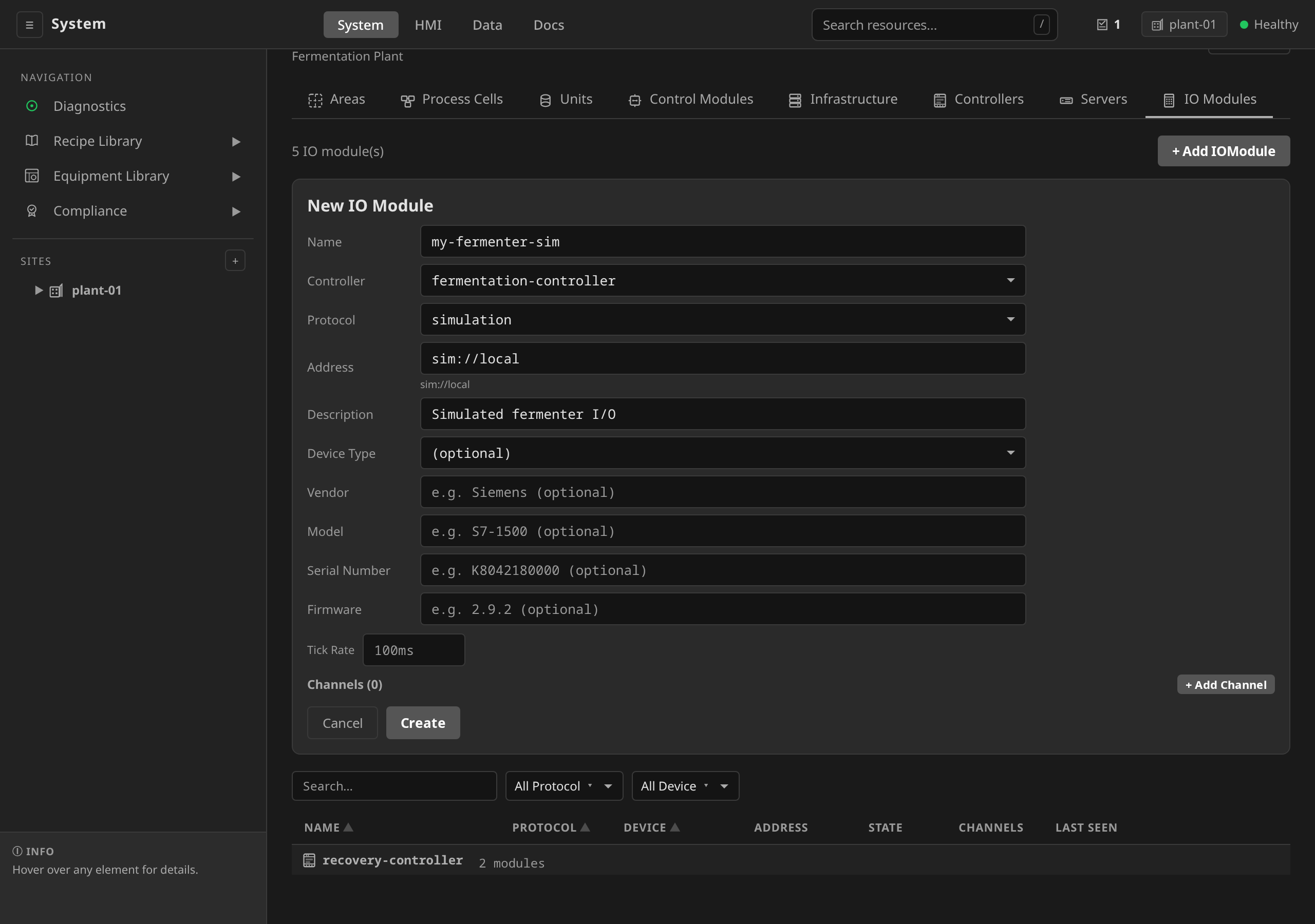
sim://local auto-fill, channel tag bindings building live, and the created module reaching Online.
dcs --site riverbend apply -f iomodule.yaml
dcs --site riverbend get iomodules my-reactor-sim
# Status should transition Unknown → Online
# examples/riverbend/06-iomodules.yaml (simulated)
apiVersion: physical.dcs.io/v1alpha1
kind: IOModule
metadata:
  name: reactor-sim
  namespace: site-riverbend
spec:
  controllerRef: pharma-controller
  protocol: simulation
  address: sim://local
  description: "Simulated reactor I/O"
  channels:
    - name: DO0
      direction: output
      signalType: digital
      address: discrete.0
    - name: DI0
      direction: input
      signalType: digital
      address: discrete.1
    # ... 16 more analog + discrete channels ...
  simulation:
    # physics model from a SimulationPreset — behaviors drive analog
    # channels from actuator commands, e.g. temp rises when jacket
    # heats up. addressMap binds the preset's generic address names
    # to this module's real tag addresses.
    preset: jacketed-reactor
    addressMap:
      temperature_pv: reactor-sim:analog.0
      jacket_sp: reactor-sim:analog.1
      # ... one entry per generic address used by the preset ...
    # (see Simulation Presets below)
Opening a secured session
A real OPC UA server is secured, and a correctly provisioned CODESYS
controller advertises no unsecured endpoint at all. The module names the
session it wants through spec.security. Those are the same five fields a
smart Unit's serviceBinding.security carries. A Secret in the module's own
namespace holds the credentials (ADR 0087).
The physical operator projects that Secret into the unit-runtime pod and the
io-probe pod, and the driver reads it there. The password stays in the
Secret. The IOModule, the ConfigMap the pods read and the gateway's
responses all carry only its name.
# examples/supervised-skid/00-credentials.yaml
apiVersion: v1
kind: Secret
metadata:
  name: skid-analyser-opcua
  namespace: site-supervised-skid
stringData:
  username: dcs-reader
  password: "<from the vault>"
  clientCert: |
    -----BEGIN CERTIFICATE-----
    ...the runtime's client identity, trusted by the server...
    -----END CERTIFICATE-----
  clientKey: |
    -----BEGIN RSA PRIVATE KEY-----
    ...
    -----END RSA PRIVATE KEY-----
---
apiVersion: physical.dcs.io/v1alpha1
kind: IOModule
metadata:
  name: skid-analyser
  namespace: site-supervised-skid
spec:
  protocol: opcua
  address: opc.tcp://skid-analyser.host.example:4840
  security:
    securityPolicy: Basic256Sha256
    securityMode: SignAndEncrypt
    authMode: username
    credentialsRef:
      name: skid-analyser-opcua
    # The fingerprint the discovery wizard reported for this server.
    serverCertSha256Pin: "3f2a...c9"
dcs --site supervised-skid apply -f 00-credentials.yaml
dcs --site supervised-skid io list skid-analyser
# Session security (spec.security)
#   Policy / mode:   Basic256Sha256 / SignAndEncrypt
#   Authentication:  username
#   Secret:          skid-analyser-opcua
#   Server cert pin: 3f2a...c9
# Credentials: in a Secret
Not yet in the UI
The IOModule form does not author spec.security, because the one
thing it must never offer is a password field. The block is written
by the discovery wizard (#1913)
or by YAML. The module's detail page shows it read-only, as a
Session security section with the tuple, the Secret's name and
the credentials verdict.
Which keys the Secret needs follows from the tuple. A username token
needs username and password. A Sign or SignAndEncrypt channel, or a
certificate token, needs clientCert and clientKey in PEM. A Secret
short a key is refused by the driver at construction with a sentence naming
the Secret and the key, and the module's CredentialsSecured condition says
the same on the record.
A module authored before this field existed carries username and
password in spec.options. Those keys still open the session, because a
running plant does not stop on upgrade, but the module reports
CredentialsSecured=False/PlaintextInSpec everywhere the condition is
served, and a deployment that has moved every module to a Secret sets
ioSecurity.refusePlaintextCredentials: true in the chart, after which the
driver refuses them in both pods. spec.security beside any of the old
security keys is refused at admission: two declarations of one session's
posture that could disagree is what ADR 0057
exists to prevent.
Two pods open the session, and a Secret volume cannot be added to a pod that
is running. The unit-runtime pod is recreated when the set of Secrets its
modules name changes. The io-probe pod is not, because it serves every module
on its controller and a recreate opens a read gap on all of them: the module
reports ProbeNotProjected and names dcs io probe restart, and a person
decides when.
Sim vs real — what changes
Switching the IOModule from sim to real hardware is a few-field edit on the same resource shape. The + Add IOModule form stays the same. The protocol dropdown decides which protocol-specific fields appear:
protocol: simulation, address: sim://local,
controllerRef: pharma-controller, inline spec.simulation
physics preset, and a single Tick Rate field. No protocol
options or diagnostic-address columns.
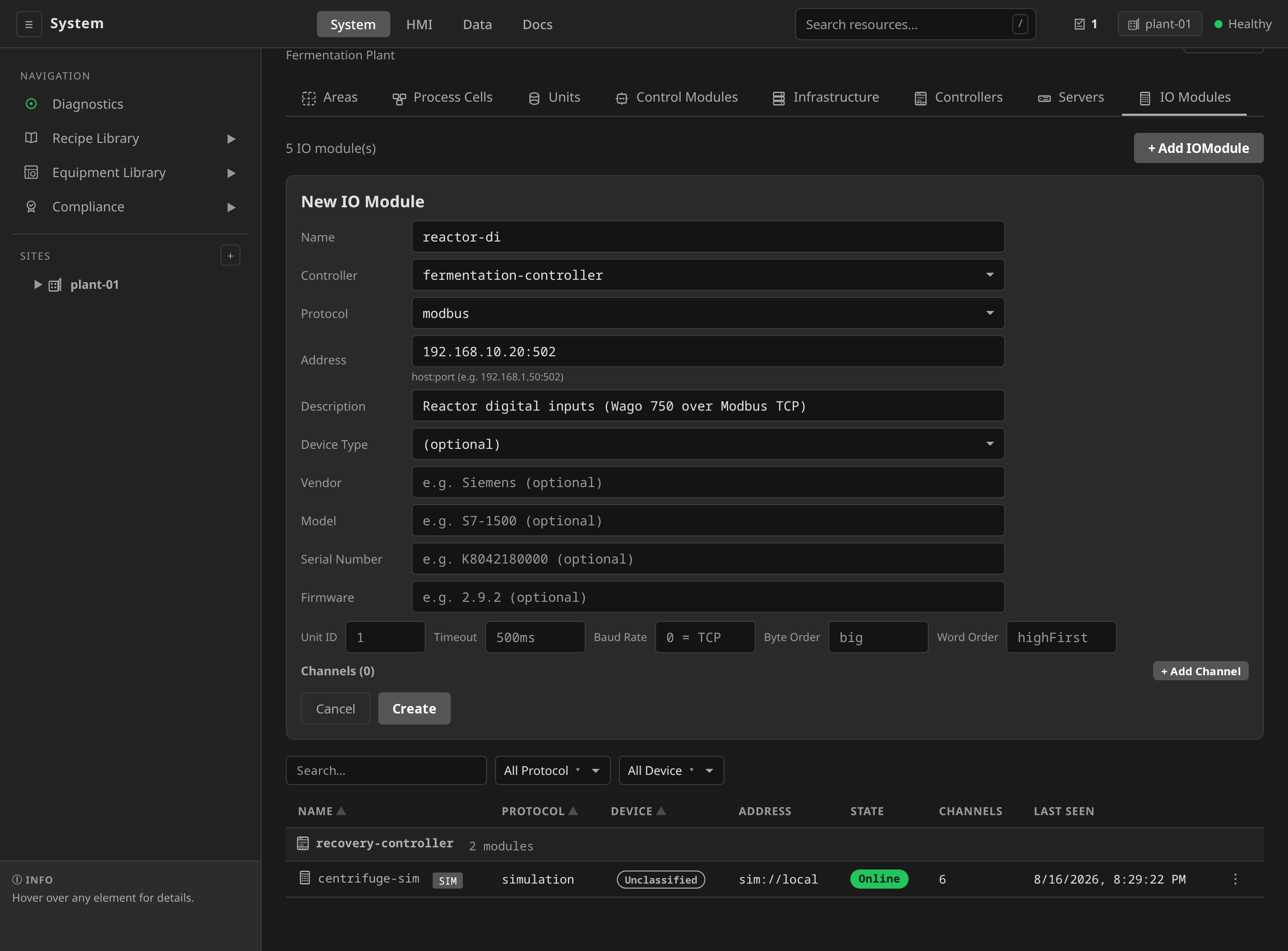
protocol: modbus (or ethernetip, opcua),
address: <ip>:<port>, no spec.simulation block, an options
block (unitID, timeout, byteOrder, wordOrder), and per-channel
diagnosticAddress for hardware wire-break / channel-fault bits.
controllerRef is optional for these network protocols (ADR
0021). A network-reached device is read over the wire by an existing
runtime node and owns no compute node of its own, so you may leave
controllerRef unset. The module is then monitored by a
namespace-shared network-io-probe pod. Set controllerRef only
when you want the module pinned to a
specific device node's probe. controllerRef remains required for
protocol: simulation, whose liveness comes from the simulation
Controller's heartbeat.
On a zoned OT network the shared probe's default placement is not
enough: only the nodes carrying field-network interfaces can reach
the device, and a probe scheduled elsewhere reads the module
Fault with nothing wrong except placement. Declare
spec.probePlacement.nodeSelector with the reach label your
deployment applies to those nodes (ADR 0042). Modules sharing a
selector share one probe pod, and the scheduler moves it to another
matching node if its current one dies. The field is refused on a
module that names a controllerRef, where the probe is already
pinned to the Controller's node.
The channel address field stays the same conceptual shape
(<type>.N) but now maps onto real hardware registers. For Modbus the
type names the register class directly: coil.N (writable coils),
discrete.N (read-only discrete inputs), and holding.N / input.N
(analog holding/input registers). There is no analog.N on Modbus.
For EtherNet/IP the address maps to a specific assembly slot, and for
OPC UA to a NodeId. The driver translates.
The same example as above, this time running against a Wago 750-series I/O coupler over Modbus TCP on a real plant network:
Same + Add IOModule form as above, but pick Protocol
modbus, paste the device's <ip>:<port> into Address, and
pick the controller node that's wired into the device subnet. The
protocol-specific options block (unitID, timeout, byteOrder,
wordOrder) appears under the address row.
dcs --site newark-plant apply -f iomodule.yaml
dcs --site newark-plant get iomodules reactor-di
# Validated=true means the observed channels match the spec
# examples/newark-plant/11-iomodules.yaml (real hardware)
apiVersion: physical.dcs.io/v1alpha1
kind: IOModule
metadata:
  name: reactor-di            # name change is optional; keep if helpful
  namespace: site-newark-plant
spec:
  controllerRef: plc-reactor-1    # the controller node running the runtime
  protocol: modbus                # was: simulation
  address: 192.168.10.20:502      # was: sim://local
  description: "Reactor digital inputs"
  channels:
    - name: DI0
      direction: input
      signalType: digital
      address: discrete.0        # addresses relative to this module
      diagnosticAddress: discrete.1   # Wago wire-break diagnostic bit
    - name: DI1
      direction: input
      signalType: digital
      address: discrete.2
      diagnosticAddress: discrete.3
    # ... real channels as wired on the physical coupler ...
  options:
    unitID: "1"              # Modbus slave ID
    timeout: "500ms"
  # NO spec.simulation block — this is real hardware
32-bit and wider values
Modbus exchanges 16-bit registers, and it says nothing about what a pair of them means together. A device that reports a flow rate as a 32-bit float puts it in two consecutive registers, and its manual is the only place that says which of the two comes first, and which byte comes first inside each one. Nothing on the wire carries that. So the address says how wide the value is, and two options on the IOModule say how the device lays it out.
A bare address is one unsigned 16-bit register. That is what every address written before the width suffix existed meant, and it still means exactly that. No existing IOModule changes behaviour. A width suffix goes on the end, after a colon:
Channel address |
Registers read | Value |
|---|---|---|
holding.100 |
100 | unsigned 16-bit |
holding.100:uint16 |
100 | the same thing, spelled out |
holding.100:int16 |
100 | signed 16-bit |
holding.100:uint32 |
100-101 | unsigned 32-bit |
holding.100:int32 |
100-101 | signed 32-bit |
holding.100:float32 |
100-101 | IEEE-754 single |
holding.100:uint64 |
100-103 | unsigned 64-bit |
holding.100:int64 |
100-103 | signed 64-bit |
holding.100:float64 |
100-103 | IEEE-754 double |
input.N takes the same suffixes and stays read-only. A coil or a
discrete input carries a single bit, so a suffix on one is refused.
The layout is two independent choices, and both are properties of the device:
| Option | Values | What it changes |
|---|---|---|
wordOrder |
highFirst (default), lowFirst |
Which register holds the high half |
byteOrder |
big (default), little |
Byte order inside each register |
Vendor manuals usually print the four combinations as ABCD, CDAB,
BADC and DCBA. Here is 123.456 as a float32, so you can match a
manual against a capture:
| Manual says | byteOrder |
wordOrder |
Registers on the wire |
|---|---|---|---|
ABCD |
big |
highFirst |
0x42F6 0xE979 |
CDAB |
big |
lowFirst |
0xE979 0x42F6 |
BADC |
little |
highFirst |
0xF642 0x79E9 |
DCBA |
little |
lowFirst |
0x79E9 0xF642 |
The defaults are standard Modbus order and are what the reference rig
was commissioned on, so a module that names neither key keeps the
encoding it has today. Note that byteOrder applies to single registers
as well: setting it to little changes what holding.100 reads, and
what holding.100:float32 reads with it.
Getting either one wrong produces a wrong number and no error. The
device answers, the registers arrive, and they assemble into
something. A reading that is enormous, near zero, or jumps between two
unrelated magnitudes as the process moves is almost always word order.
Read the two registers one at a time with dcs io read <module>
holding.100 and holding.101 (bare addresses that come back as raw
16-bit words), and compare them against the table above.
Diagnose word order on an input. A bare address is read exactly as
written. That is what makes it the right probe here. It is also why it
is the wrong place to read an output on a device whose read and write
address tables differ. A WAGO coupler answers a read of an output's
write address from the analog input image, so the two registers you
compared would belong to a different card
(#1689).
Read an output back through its channel name, or at the channel's
declared readbackAddress.
An option this driver does not implement is refused when the module is built, with the accepted keys named in the error. A typo and a capability that does not exist are the same thing to a driver, and both used to be dropped in silence.
Where an output reads back
A Modbus address is a number, and nothing in the protocol says that the
number you write is the number you read. Some couplers publish two
address tables. A WAGO 750-series coupler is one: an analog output
written at holding.0 reads back at holding.512, and reading it at
holding.0 returns the analog input process image instead. The
manual states it in prose, as an offset of 0x0200 added to the address
to read an output back.
Left alone that is an invisible fault. Both areas carry the same
left-justified 0-32767 span. The value is therefore in range, its
quality is Good, and nothing reports an error. What you see is a
plausible number belonging to a different card
(#1689).
A channel therefore declares where it reads back:
channels:
  - name: AO0
    direction: output
    signalType: analog
    address: holding.0             # what a write targets
    readbackAddress: holding.512   # what a read comes from
Auto-discovery fills this in for you. The WAGO device profile emits a
readbackAddress for every output it discovers, so a module discovered
by a version that knows about the split already carries it. Leave it
unset for a device whose outputs read back in place, which is most of
them.
A module whose channels were discovered before that carries none, and
none of it looks wrong. Its outputs are still read at their write
addresses, which is the fault this section opens with. Upgrading on its
own does not move them. The product reports the disagreement in two
places. An output whose device declares a readback address its channel
does not carries a note under its address in the channel table, naming
the register and asking for a fresh discovery. The IOModule reports
status.validated: false for as long as the two disagree.
The remedy is Discover Channels on the IOModule, which rescans the
device and rewrites spec.channels with the addresses it reports. Do it
once per module after an upgrade that first taught the product about the
device.
Two things behave the way they read. A channel name is the
abstraction over the channel, so dcs io read <module> AO0 follows the
readback address and reports what the output is actually holding. A
bare address names one register and is never redirected, so
dcs io read <module> holding.0 still reads exactly that register.
That is what makes the bare form the right tool for telling the two
tables apart on a device you are commissioning.
The readback trails the write. On the WAGO coupler an output write shows up at its readback register within about 10 ms. A read issued in the same breath as the write can still answer with the pre-write value. Two CLI invocations are far enough apart that a person never meets this. A program that verifies its own write in the same code path has to allow for it.
When a card reports its own broken wire
A 4-20 mA loop carries a live zero so that a failed transmitter is distinguishable from a real zero. The card usually takes that away before the driver ever sees it. WAGO's analog input modules map 4 mA onto raw zero and 20 mA onto 32767, so the current NAMUR NE 43 reserves for the fault band has already been normalised out of the number the register holds.
What survives below 4 mA is whatever the card chooses to report there. On WAGO's standard analog input cards it is a diagnostic, and the card publishes it inside the measurement word itself. There is no second address to read. The card carries a 12-bit measured value in bits 14 down to 3 and hands the low bits to its own range detection. A 750-454 sets bits 0 and 1 together for measurement range underflow or a broken wire, and it sets bit 0 alone for overrange. A 750-459 sets the same two bits at either end of its range.
The number that follows from this is worth reading twice. Every measurement such a card can produce is a multiple of eight, because the whole of it sits above the three low bits. The bench recorded an open loop at raw count 3, which is not a multiple of eight and was therefore never a measurement (#1734). The card had been saying "broken wire" for thirty-one seconds, inside a number the product was scaling into engineering units.
The driver reads those bits now and reports Bad quality
(#1740).
Nothing is declared to get it. The device profile that identifies the
card also carries which bits that card defines, so an IOModule discovered
against a WAGO coupler behaves this way with no field in its spec and no
change to an existing document.
From there the condition travels the path
ADR 0074
already built. An AI or DI block reading Bad holds OUT at the last
value it trusted, raises PV_BAD, and faults. The control program
therefore reports Degraded with the block named. A PID wired for
PV_BAD holds its output. Without that wire it would go on integrating
against a dead instrument. A device interlock reading that tag trips. The tag reads Bad on the HMI,
through dcs io read, and in the channel table on the IOModule detail
page. A tag bound to the block's OUT reads Bad too, for as long as
PV_BAD is raised. The held value therefore never reaches the HMI or
the historian as a measurement (#1920).
A channel the plant knows is empty is declared on the ControlModule as
an unconnectedInputs entry, and its block then holds and flags a Bad
reading without faulting. The declaration reaches an AI or a DI.
A digital contact leaves no other evidence of its own failure: there is
no out-of-range for a bit, so a broken wire on a normally-open switch
reads exactly like a switch that is open. See
Control Modules.
Three limits are worth stating plainly.
- Only a card whose manual documents the bits claims them. Bit 2 is not read on either card above, because one manual calls it unused and the other calls it reserved with no defined value. An RTD card's low bits are tenths of a degree and it declares no mask at all.
- A wide read cannot carry it. The bits are the low bits of one
16-bit register, so an address with a
:uint32or wider suffix reads a second register into the same value and the mask no longer names anything. The driver answers such a read the way it always did. - This is not every card. A device family whose profile the product
does not carry, or a card that publishes nothing below its range, is
still covered only by the
AIblock's optionalrawFailLowandrawFailHighband. That band is a property of one card measured once, and ADR 0074 says why it must not be documented as the general answer.
It is a different mechanism from diagnosticAddress, and the two cover
different hardware.
| Where the fault is published | Declared by | |
|---|---|---|
diagnosticAddress |
A second address, such as a 750-436 digital input card's per-channel wire-break bit at its own discrete.N |
The channel, in spec.channels |
| In-band fault bits | Inside the same word as the measurement, on a card that carries its range diagnostic there | The device profile, from the card's manual |
When one channel stops reading
A channel can stop answering while the rest of its module keeps
answering. A timeout on one register, a fenced runtime, a card pulled
from a live lineup: each of those comes back inside a successful
response, as Bad quality against that one address, beside neighbours
that read normally.
The channel table on the IOModule detail page says so in three places (#1866). The Quality cell reports what the address answered, and carries the driver's own message as a tooltip. The Value cell keeps the last reading that was good, dimmed. Keeping it is deliberate, because that number is the only account anyone has of where the plant was. Dimming it is deliberate for the same reason, because it is no longer a measurement of anything. The Last Read cell keeps the timestamp of that reading and goes on ageing, turning red past ten seconds.
The header keeps reading LIVE and gains a count of the channels that
are not reading. The module is answering, so reporting it offline would
be a different false statement about equipment.
Until that issue the row said none of it. The value stood at its last
good reading, the quality cell went on reporting the Good it had been
told minutes earlier, and the relative time in the last column was the
only cue anywhere on the page. Measured on the bench during a safe-state
fence, the cell held 16384 for the whole window while the coupler sat
at zero.
When a variable is a structure
An OPC UA server can declare a variable as a record of its own: the
boiler simulator's BoilerStatus is a BoilerDataType, a subtype of
Structure, and a CODESYS controller can publish a whole STRUCT the
same way. The runtime reads scalars. It publishes such a variable as no
value at Bad quality, with a reason that names the type, on the tags
endpoint and on the ControlModule page
(#1943).
Discovery types the variable Structure and says on its row that the
runtime reads no value from it. Until that issue the wizard typed it
String and the page printed the undecoded object. A structure the
plant needs read is a per-field variable on the server, which every
controller's symbol configuration can expose.
When discovery stops short of the whole node
Auto-discovery on a WAGO coupler reads the module identification table and walks the lineup left to right, adding up how much process image each card occupies. Every address it hands you is the running total of the cards in front of it, so one card whose width the profile cannot size moves every card behind it in that image.
The coupler publishes each digital card's size in its identification word, so those are never in doubt. It publishes only a part number for an analog or complex card, and two things can leave that unresolved: a card configurable for more than one channel count, such as the 750-464, and a card the shipped catalog does not carry. For those the profile reads the node's own analog process image totals and subtracts the cards it does know, which names the remaining one exactly.
Where that arithmetic does not settle it, discovery stops at the ambiguous card. Guessing past one would move every address behind it. You get every channel in front of it, with correct addresses, and the io-probe logs what it declined to place and why:
Device profile discovery is incomplete  profile="WAGO 750-series" channels=10
  notDiscovered=["slot 3: 750-464 is parametrised for 2 channels or 4 channels
  and the identification word carries neither"]
Three answers to that message, in order of preference. Declare the
channels yourself in spec.channels, since a hand-authored address is
never in doubt. Add the card to the profile catalog if it is a card the
product should know. Or read the coupler's own web interface for the
node's analog word counts and confirm the arithmetic there.
A node where nothing at all could be placed falls back to the process image totals, which give every address in the node and name no card. The channels are correct and carry no raw span and no fault mask, because a total says nothing about which card is behind it.
What kind of device is at the far end
The protocol says how the product reaches a box. It has never said what
the box is, and the difference matters: a Wago coupler carries the
channels you wired into it, while a Siemens S7 at the same Modbus
address is running its own program that nobody here authored. Both are
IOModule resources, because both are endpoints the runtime exchanges
process data with, and the optional spec.fieldDevice record is what
tells them apart.
spec.fieldDevice.type |
What it means |
|---|---|
io-module |
A passive card, coupler or remote-I/O head. It runs no program; its channels are the process data. |
control-device |
A peer controller running its own program that the product neither authors nor executes. Tags are exchanged as equals. |
instrument |
A smart instrument or analyzer that speaks a network protocol in its own right, with no coupler in front of it. |
gateway |
A protocol converter or aggregating server fronting other devices. The tags are real; the box at the address is not the box the signal came from. |
The record also carries vendor, model, serialNumber and
firmware. That is the nameplate a maintenance engineer wants when a
device stops answering. Vendor and model name the product. The serial
number names the one unit standing in the plant, which is what a work
order is opened against. Nothing in the runtime, the drivers or the
recipe vocabulary branches on any of it. Classifying a device changes
what the product can tell you about it and never how a tag is read.
The classification is declared and never inferred. A module named
siemens-plc-01 is not a control device until somebody says so, and an
IOModule with no fieldDevice block reads as Unclassified in the
Device column of the IO Modules sub-tab. Nothing sorts it
into a bucket on the strength of its name. Filling the block in is the
fix. Every IOModule authored before the field existed is unclassified,
which is honest: nobody has looked at those boxes yet.
Two rules bound what a device record is for (ADR 0033):
- The box stays out of the ISA-88 process tree. Its tags enter it.
A field device's tags become
ControlModuleinstances, exactly as device discovery already emits them. Classifying a box gives it no state machine, no phases, and nothing a recipe binds to. - One physical thing gets one record. A vendor skid orchestrated
through
Unit.spec.serviceBindingis already a citizen of the process tree, so it needs no device record of its own. Where an IOModule addresses the same host as such a Unit, the reconciler says so onstatus.conditions[type=DistinctAssetRecord]and the row is marked already in the process tree: the module is that skid's data plane, and the Unit is the box.
Worked examples of all four types, including the skid case, are in
examples/field-devices/iomodules.yaml.
A smart instrument's own identity
An IOModule's record describes the box the runtime opens a connection
to. A smart instrument reached through a shared endpoint is not that
box. Its nameplate lives on the ControlModule that models it, in a
spec.fieldDevice record of the same shape
(ADR 0043).
Device discovery writes one for every PA-DIM
instrument it emits, and the module's Device section reads it back
and edits it.
Both records are served on their resource's API, which is what lets a maintenance system resolve a device-health alarm to a physical asset: the alarm names a control module, the control module names a serial number, and the work order is opened against that. The serial is the field the two records never share. A shared endpoint's IOModule carries the instrument's vendor and model when there is exactly one device behind it, and never its serial, because one unit identity recorded in two places is one that can drift.
A controller's program identity
A control-device runs a program nobody here authored, and the nameplate
on its record says nothing about which build of that program is loaded.
firmware is the controller's own software revision, typed in by hand or
copied from a PA-DIM nameplate at discovery, and it does not change when
an engineer downloads a new project. A batch reviewer asks which program was in
the controller while the lot ran. That is a question about the project,
and the nameplate cannot answer it.
No protocol the product speaks answers it on its own. The CIP Identity
object, OPC UA ServerStatus.BuildInfo and Modbus function 43 each name
the device's firmware, and none of the three drivers reads even that
today. What every controller family does offer is a tag the program can
write its own identity into. A Logix controller regenerates an audit
value on every download and on every edit its change-detection mask
covers, and a GSV instruction puts it in a DINT[2] tag (Rockwell
1756-PM015, firmware 20 and later). A CODESYS application can publish a
version constant in its Symbol Configuration. A Modbus device holds
whatever register pair its program fills. Each of those is an address,
and the driver on that protocol already reads any address it is given.
The product does not read one yet, and the batch record does not carry
one. #2161
is the proposal. The IOModule declares the address under
spec.programIdentity, and the io-probe polls it into status the way it
polls NE 107 device health. The record freezes the value at batch start
and batch end, and it discloses a change the way it discloses a
failover. The record does not yet say which of the product's own function
block networks or which runtime build ran the lot either, and
#2162
is that half. Until both land, the answer to which controller program ran
a batch is the controller's own records, and nothing here.
What stays identical above the IOModule
ControlModule instances bound to this IOModule keep their
tagBindings strings identical between sim and real. Only the
IOModule name portion changes (reactor-sim:discrete.1 becomes
reactor-di:discrete.1). The addressing convention
<iomodule-name>:<channel-address> is the same on both sides. See
Instances and tag bindings
in Control Modules for the binding spec.
The name portion is what routes the read. The unit runtime splits an
address on its first colon and looks the prefix up among the IOModule
drivers it loaded for this unit, so a swap from sim to real is a swap
of which driver answers. An address with no prefix reaches neither: it
is served by the runtime's own default driver, which is an
unconfigured simulation driver. That driver answers an address it has
never heard of at quality Bad, with a reason saying the address is
not a channel it carries. The gateway still refuses to save a
ControlModule carrying such a binding
(ADR 0076).
A tag that reads -- for the life of a plant is a defect found late,
and the point of that refusal is to find it early. A prefix naming a
module the unit did not resolve is refused by the runtime instead, on
every read, as unknown IOModule driver.
Every layer above the ControlModule (phase templates, operation templates, unit procedure templates, master recipes) is identical bit-for-bit between sim and real. That's what makes the riverbend reference simulation a legitimate starting point for a real plant.
End-to-end bring-up workflow
The clip below walks the configured result on the reference fermentation
site: an IOModule's channels and protocol addressing, the tag-address
binding strings control modules consume, live channel values, the
inline spec.simulation binding, an audited
edit, the driver's connection and its configuration state on the
Diagnostics page, and the same signal landing on the operator's HMI
faceplate.
/system: channels and addressing, live channel values, the simulation binding, one audited edit, driver health, then the same signal on the /hmi faceplate.The typical workflow for enrolling a new piece of real equipment:
-
Enroll the controller device. Follow the Device Enrollment guide: join the device to the cluster at the deployment layer, then register it. This gives you a
Controllerresource bound to a matching Kubernetes node. -
Author the IOModule. Write a YAML file describing the physical I/O: protocol, network address, channel list with real addresses. For Wago Modbus, each channel's
addressis the relative coil or register offset within the coupler's address space. For Rockwell EtherNet/IP point I/O, it's the assembly slot. For OPC UA, it's the node path. -
Apply the IOModule. The physical-operator reconciles the IOModule and the unit-runtime on the target controller attempts to open a connection.
/system→ Site (left sidebar) → IO Modules sub-tab → + Add IOModule. The same form as in Authoring an IOModule. Fill in the fields from theiomodule.yamlyou authored in step 2 (protocol, network address, the channel list with real addresses). Create. TheSTATEcolumn transitionsUnknown→Online.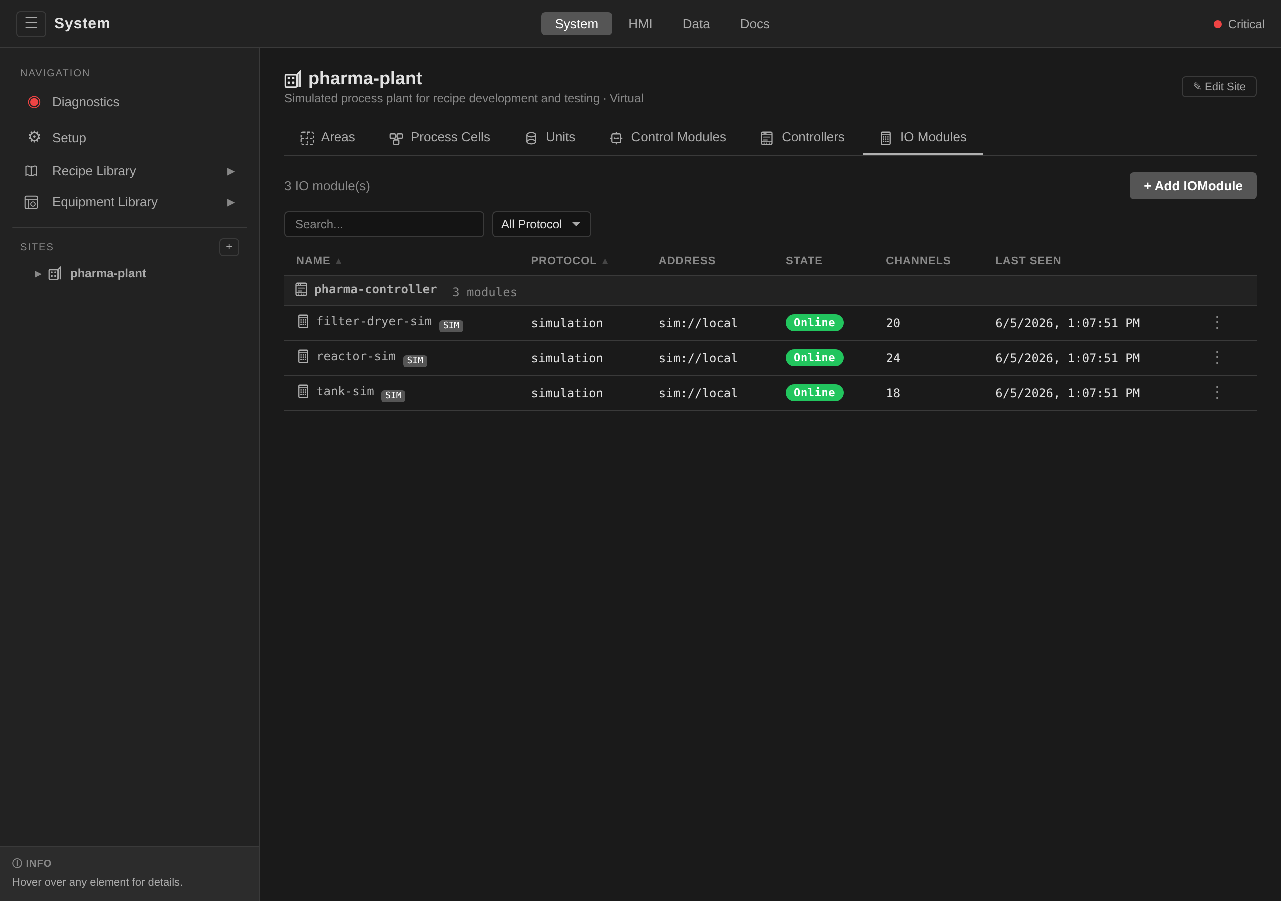
dcs --site newark-plant apply -f iomodule.yaml
dcs --site newark-plant get iomodules reactor-di
# Status should transition Unknown → Online
# Validated=true means the observed channels match the spec
Apply the
iomodule.yamlauthored in step 2:dcs --site newark-plant apply -f iomodule.yaml -
Author ControlModule instances and run a phase against them. Each piece of field equipment (valve, sensor, motor) gets its own
ControlModulewithtagBindingsthat point at IOModule channels. Once those are live, aMasterRecipecalling an existing phase template runs against real hardware without modification. See Instances and tag bindings in Control Modules for the full instance-authoring flow, and Recipes for the recipe layer above. -
Wire alarms. Copy the riverbend alarm patterns for this unit. Discrete-valve MISMATCH alarms, IOModule
StateEquals: Fault, hardware-limit alarms on safety-critical PVs. See Alarms and Interlocks for the full patterns, and tunedebounceSecondsto match your real valve travel times.
Simulation Presets
Simulation Presets are reusable equipment-behaviour models with generic
address names (e.g. temperature_pv). A simulation IOModule references
a preset and supplies an addressMap to translate the generic names to
real I/O addresses. The unit controller expands the preset at reconcile
time and forwards the flattened behaviours to the runtime, so the same
virtual equipment can back multiple simulation or validation runs without a
per-instance CRD.
The clip below walks the whole virtual-commissioning loop on site plant-01: authoring a preset for a utility skid that does not physically exist (behavior types and parameters typed in the browser), binding it onto a simulation IOModule's channels through the address map, and watching the live channel values flip from placeholder wobble to the authored process.
/system: author the glycol-loop preset, map it onto glycol-sim, and the plant behaves, with no hardware anywhere in frame./system → Equipment Library → Simulation Presets
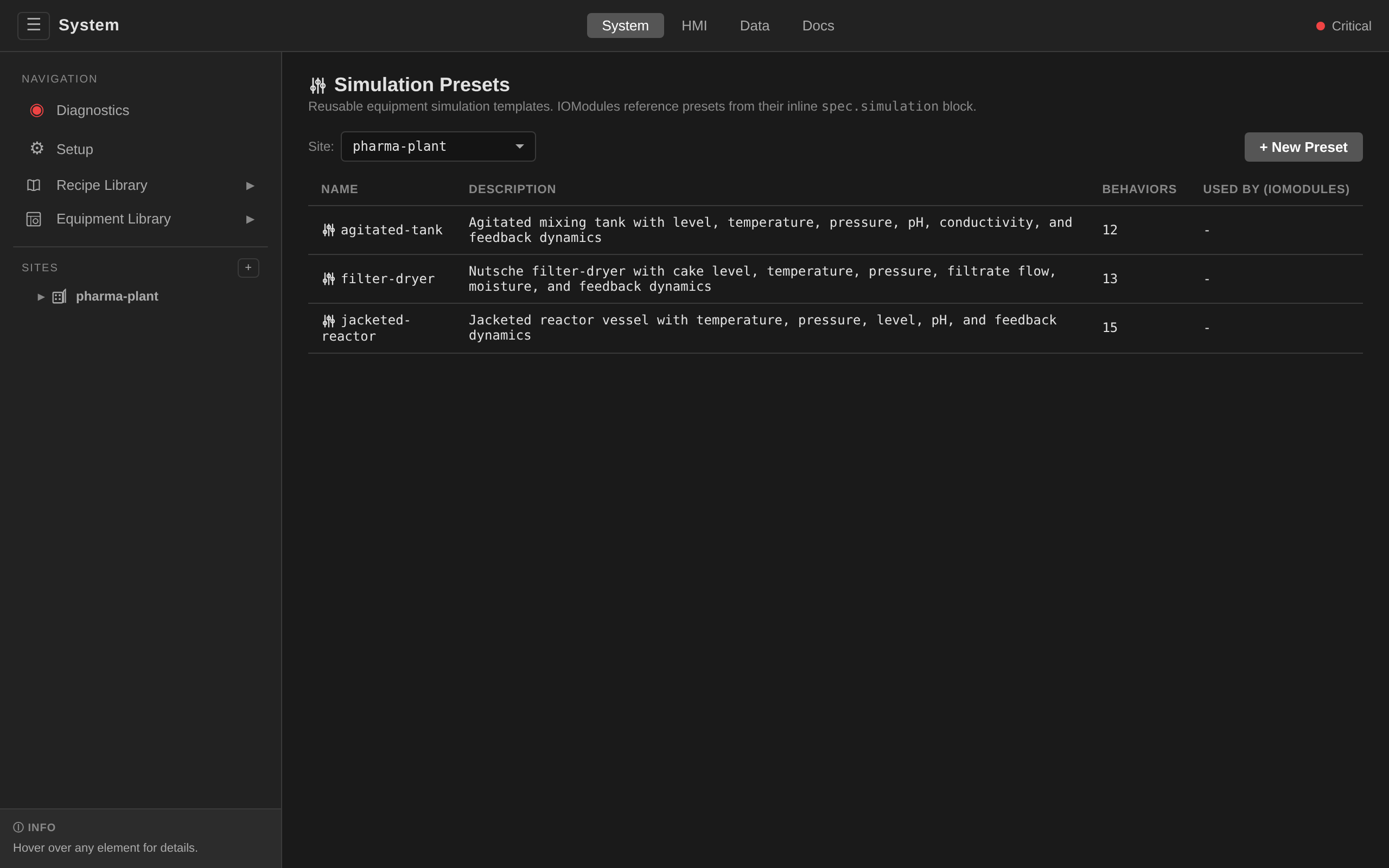
→ pick a site. The list shows each preset's behavior count
and the IOModules that reference it.
Create: click + New Preset. Enter a name and description,
then click + Add Behavior for each behavior row. Each row takes
a generic address name (e.g. temperature_pv), a behavior type from
the dropdown, and a comma-separated key=value parameter list.
Click Save.
Edit / Delete: click a preset to open its detail view. The ✎ Edit and ✕ Delete buttons are in the top right. Editing an in-use preset takes effect on the next reconcile of each referencing IOModule.
Each of these controls is drawn only for a session whose resolved
action set carries the action behind it. + New Preset names
simulationpreset:create, Edit names simulationpreset:update,
Delete names simulationpreset:delete, and the Seed Built-in
Presets button on an empty list names simulationpreset:seed. All
four sit at the engineer tier. The list and the detail view are
reads and stay available either way. dcs auth entitlements reports
what the session holds.
Reference from an IOModule: open a simulation IOModule
(protocol: simulation), click Edit, and use the Simulation
section. Pick a preset from the dropdown, then map each of its
generic addresses onto a real channel address on this module (the
field suggests the module's own discovered channel addresses). The
form requires every preset address to be mapped before Save.
An unmapped generic address would resolve to a dead tag at runtime.
Inline behaviors and faults authored via dcs apply carry through
the edit unchanged.
dcs apply -f reactor-sim.yaml
dcs get simulationpresets -s $SITE
apiVersion: physical.dcs.io/v1alpha1
kind: SimulationPreset
metadata:
  name: reactor-sim
  namespace: site-demo
spec:
  description: "Jacketed reactor with temperature and level dynamics"
  behaviors:
    - address: temperature_pv
      type: PIDResponse
      params:
        coAddr: jacket_sp
        gain: "1.0"
        timeConstantSec: "300.0"
        engMin: "0"
        engMax: "150"
    - address: level
      type: TankLevel
      params:
        inFlowAddr: inlet_flow
        outFlowAddr: outlet_flow
        capacity: "1000.0"
        maxFlowRate: "1.0"
Behavior type values come from the SimBehaviorDef enum: SineWave,
RandomWalk, NoisyConstant, DigitalPulse, TemperatureRamp,
ValveFeedback, TankLevel, PIDResponse, Expr. Each type takes its
own parameters. See the built-in presets for idiomatic examples. Every
behavior stores its output in engineering units by default, so the channel
table reads believable values. Add raw: "true" to a behavior's params to
model raw ADC counts (0–65535 scaled from engMin/engMax) when you want an
AI block to exercise a real raw-to-engineering conversion.
Every behavior writes its own address on the first scan. That includes a behavior modelling a track toward a target that starts out already at it. A valve nobody has commanded reads 0%. That is where the valve is, and it is a reading. So a channel a behavior names carries a value from the moment the runtime starts.
A parameter you leave out takes the behavior's documented default. A
parameter set to a value that does not parse is refused when the preset or
the IOModule is saved, and the refusal names the parameter. Defaulting it
would run the tag on a number nobody wrote. An AI block also auto-discovers
its scaling from engMin/engMax, so such a mistake reaches a block whose
own configuration is correct. See
ADR 0064.
See Simulation profiles in the examples library for complete preset definitions.
Protocol cheat sheet
| Protocol | Driver | address format |
Channel address | Common quirks |
|---|---|---|---|---|
| Modbus TCP | pkg/driver/modbus |
<ip>:<port> |
coil.N (coils), discrete.N (discrete inputs), holding.N (holding registers), input.N (input registers). A holding or input register takes an optional width suffix — holding.N:float32, input.N:uint32 — covering uint16, int16, uint32, int32, float32, uint64, int64 and float64; see 32-bit values |
Unit ID via options.unitID. Register order for a value wider than one register via options.wordOrder, byte order within a register via options.byteOrder. An option this driver does not implement is refused outright. |
| EtherNet/IP (experimental — gated) | pkg/driver/ethernetip |
<ip>:<port> |
Assembly slot addresses (vendor-specific) | Generic Device Profile only. ControlLogix tags need CIP addressing. Explicit messaging only, so options.timeout is the single key it reads and an rpi has nothing to set. An option this driver does not implement is refused outright. Disabled by default. Requires --enable-experimental-drivers on unit-runtime and direct CRD authoring (no UI form). See Not customer-ready. |
| OPC UA | pkg/driver/opcua |
opc.tcp://<host>:<port> |
ns=<ns>;s=<nodeId> or browse path |
Session security through spec.security: policy, mode (None, Sign, SignAndEncrypt), authMode (anonymous, username, certificate), a credentialsRef Secret and a serverCertSha256Pin (see Opening a secured session). The two bounds via options.connectTimeout/options.requestTimeout. options.securityPolicy and options.securityMode remain for a module that declares no security block; options.username/options.password and the certFile/keyFile/caFile paths are deprecated (ADR 0087). A value that does not name a mode or a policy this client implements is refused. A defaulted typo would have silently meant no security at all (see ADR 0057). An option this driver does not implement is refused outright. Subscriptions are push-based. A write goes out in the type the node declares: the driver reads the node's DataType attribute on the first write of a connection and encodes every value to it, so the float64 an AO block hands it reaches a REAL tag as a Float and a WORD tag as a UInt16, and a value the declared type cannot hold is refused before the wire, naming the value and the type, because a truncated number landing is a different setpoint (#1910). |
| Simulation | pkg/driver/simulation |
sim://local |
analog.N, discrete.N |
Inline spec.simulation block on the IOModule drives virtual values. See Simulation profiles. options.tickRate sets how often behaviors run, options.seed makes the run reproducible, and init.<address> seeds one address at startup. An option this driver does not implement is refused outright, and so is a seed that would not seed. A behavior or fault parameter set to a value that does not parse is refused the same way, at the document (ADR 0064); an init.<address> value is not, because an address may hold a string. |
Two measurements of one device
A module's connectivity is measured twice, by two processes, over two paths. Neither can stand in for the other, and where they disagree the disagreement is the diagnosis.
| Reading | Who takes it | Where it is served |
|---|---|---|
| The unit runtime's own connection | The runtime driving the Unit, from whichever node it is bound to. This is the connection the control loop scans over | ioDrivers[].connected on GET /api/v1/sites/{site}/units/{name}/runtime/diagnostics |
status.state on the IOModule |
The io-probe. A controller-bound module's probe is a pod pinned to its Controller's node (ADR 0021); a controller-less one is served by a namespace-shared probe (ADR 0042). Neither is in the control path | dcs get iomodules, and the module's own detail page |
The gateway puts them on one row in two places: the I/O Drivers table in the Diagnose panel's Runtime tab, and the I/O In Use table on a Unit's detail page. Four pairings are worth recognising.
| Runtime connection | Module state | What it means |
|---|---|---|
| Connected | Online |
Both agree. Nothing to look at |
| Connected | Unknown |
The control loop is reading the device and the probe is not answering. Start at the probe's host. Losing the Controller a network module names is one way to reach this, because that Controller is where the probe runs |
| Connected | Fault |
The probe reached the device's endpoint and was refused while the runtime is reading it. The two take different paths to the same box, so compare them before suspecting the hardware |
| Not connected | Online |
The probe is reaching the device and this runtime is not. The fault is on the runtime's side of the wire. The two are measured on different cadences, so expect this pairing briefly at the start of an outage the runtime notices first |
A row also reports a driver the runtime holds for a module the site does not list. That is stale I/O configuration on the runtime, or a module deleted while its connection stayed open.
There is deliberately no node column on either table. For a network module,
controllerRef names where the io-probe runs and nothing about how the device
is reached, so a warning drawn from "this Unit's runtime node differs from its
I/O's controller node" would describe a dependency that does not exist. What
the runtime holds a driver for is the real dependency, and it carries no node
concept at all. That is why a controller-less module renders in these tables
exactly like any other.
Which of the two answers a live read
The channel table on an IOModule's detail page is a third path, and it is
neither of the readings above. It reads on demand, once a second by default,
and the gateway routes each batch to whichever component holds a driver for
that module: a protocol: simulation module is read through the unit runtime
of the Unit that binds it, because that is where its simulation driver runs,
and every other module is read through its Controller's io-probe.
The LIVE chip on the channels header names the one that answered. The batch
response carries the backend the gateway routed it to, and the chip reads it
there. It does not derive it a second time from the module's protocol, so what
the header says and what actually served the value cannot disagree. A response
that names no backend renders as LIVE on its own.
That the chip has to be told is worth the sentence. It used to say
LIVE via io-probe on every successful read. On a simulation module that named
a component the same page's IO-Probe block, a few lines above it, correctly
reported as absent
(#2099).
Every module on a demo or a capture stack is a simulation module, so that was
the whole of what those pages showed.
What the probe actually measures
Every fifteen seconds the io-probe dials the modules that report themselves disconnected, and reads the comm-loss fail-safe back from the ones that report themselves up. A module that answered anything has proved its connection, and the probe leaves it alone.
What counts as answering is the driver's own account of what its endpoint has said, and not the verdict of any one call. Each driver counts the exchanges its endpoint replied to, the probe reads that count before it touches the module, and a count that has moved since is traffic this connection carried.
That distinction earns its paragraph, because reading the fact off the fail-safe readback instead was wrong twice. Nothing on this cadence performs a readback for an EtherNet/IP module at all (#1759). And a Modbus device that no device profile claims answers the register read the profile lookup makes, and then fails the readback anyway. The readback reports whether a fail-safe was read, which is a narrower question than whether anything was (#1763). That is every Modbus device in the field that is not a WAGO 750-series coupler, and each of them had its connection torn down and re-established every fifteen seconds for as long as it ran, moments after it had spoken.
A module that answers nothing is asked directly, and the result of that is the
reading. An ask that reaches the device says the device is there and simply had
nothing to say. An ask that does not reach it is the module going Fault, which
is what raises the equipment alarm and Holds the running units that depend on
it.
The ask exists because a connected flag is not a measurement. A driver sets it
when it dials and clears it when an exchange fails, and nothing tells a TCP
socket that the cable at the far end has been pulled. Before this the probe read
that flag and performed no exchange of its own, so a module whose bus had been
cut reported Online with lastSeen advancing for as long as anyone cared to
look, and Fault was unreachable for a network module
(#1755).
What the ask is differs by protocol. Each driver uses the cheapest exchange its protocol gives it, and for two of them that is a different thing.
CIP obliges every device to answer a read of its Identity object. An EtherNet/IP module is therefore asked over the session the probe already holds, and it keeps that session when it answers. A device that does not answer has its session re-established, so the re-dial is the remedy for a dead connection and never the question put to a live one (#1759).
Modbus standardises no register any device is obliged to answer. There is no read to fall back on, so a fresh dial is the only exchange available and a Modbus module is dialled again. The connection that drops has carried nothing since the probe last asked, which is why the probe is asking. The exchange count above is what makes that true.
Not every driver needs asking. An OPC UA client follows its own session state
and an in-process simulation driver has no far end to lose, so both keep the
flag honest without an exchange. The module's ConnectivityMeasured condition
says which case a reading came from, so the difference is recorded rather than
assumed.
That condition records the exchanges a pass performed. A device that answered the fail-safe readback is recorded as measured, and so is one whose driver counted an answer, even though no verify was asked of either. The exchange is the measurement a verify would have gone and taken. Until #1826 only the deliberate work counted. The strongest evidence a device can offer was therefore also what suppressed the verdict, and the one module on a stack that a probe genuinely exchanged telegrams with was the one module reporting that nothing had.
An exchange a person performs through the API is not one the pass performed,
and it does not count. A dcs io read, a tag poll from the module's page and
a commissioning write all reach the device through the same probe, and until
#1931 the
pass they happened to land inside recorded the module as measured. On a
Modbus or EtherNet/IP module nothing changed, because the readback or the
verify says the same thing on every pass. On an OPC UA module the probe never
asks, that read was the only road to measured, so the condition followed
whoever was looking at the module. The bench CC100 read
ConnectivityMeasured=True/ProbeReachedDevice on its record and "this probe
performed no exchange with the device" from dcs io list cc100 inside the
same minute, and both were faithful to the pass they read. A condition that
answers to who is looking is not a property of the module. An OPC UA module
that is up now reads reported by driver on every pass. It reads measured
only on a pass the probe dialled it.
ConnectivityMeasured answers a second question, which the state beside it
cannot. A module reads Unknown when the DCS has no measurement of it, and
there are two ways to have none: nothing has asked yet, or something was asking
and has stopped. The condition reads NoMeasurementTaken for the first and
MeasurementLost for the second, and the module page prints them beside State
as not measured and measurement lost.
Every module the product creates passes through the first. The discovery
wizard's Apply emits an IOModule that is Unknown in the same second, and the
probe reaches the device about a minute later. Until
#2064 both
cases carried NoMeasurementTaken, because every Unknown reading arrives with
nothing measured whether or not anything was measuring before. The alarm
generator raises a Medium System alarm for a probe that is not answering, so it
annunciated one against every new module on its way in. The distinction is drawn
from the condition already on the module: a reason that is not
NoMeasurementTaken is a measurement this module has already had. That makes
MeasurementLost sticky, which is correct. A module measured once was measured
once, however long ago the instrument went away.
A simulation module is never recorded as measured. The device is this process,
so there is no far end an exchange could have reached. No probe pod serves one
either. It reads Online on its Controller's heartbeat and reports that its
connectivity is what the driver says
(ADR 0075).
Every demo, training and docs deployment is protocol: simulation throughout.
This is therefore the case most readers meet first.
Which build of the probe is answering
A chart upgrade rolls every operator Deployment. The io-probe pod is not
chart-managed: the physical operator creates it once, and it keeps the image the
operator that created it chose. It stays Running and Ready on that image, and
every module it serves keeps reporting Online. An upgrade that has stopped at
the control plane therefore reads exactly like a finished one
(#1765). Pod
age says nothing either. A probe recreated by the old operator during a node boot
minutes before the upgrade is seconds old and still superseded.
Every IOModule therefore carries an IOProbeImageDrift condition. True means
the pod named in its message is running an image the operator would not create it
with today. dcs_ioprobe_image_drift carries the same fact as one series per
probe. Unknown means no probe serves the module, or its pod could not be read.
That is a statement about the instrument, and it says nothing about the image.
The product reports it. dcs io list and dcs get iomodules carry a PROBE
column reading current, superseded, unread or no probe, and a site with
anything superseded gets a line under the table naming the distinct pods. That
line is deduped on purpose. One probe serves many modules, so six superseded
cells can be one stale pod or six, and the restart is one call per pod.
$ dcs --site newark-plant io list
NAME             CONTROLLER        PROTOCOL  STATE   CHANNELS  FAIL-SAFE  PROBE
granulator-di    plc-granulator-1  modbus    Online  4         clear 2s   superseded
granulator-do    plc-granulator-1  modbus    Online  8         clear 2s   superseded
granulator-plc   plc-granulator-1  opcua     Online  12        (n/a)      current

1 io-probe pod is running an image this operator would not create them with.
  plc-granulator-1-io-probe — restart with: dcs io probe restart granulator-di --reason "…"
dcs io list <module> prints the pod, the verdict and the reconciler's own
sentence, and the IOModule detail page in the engineering UI carries the same
three facts in an IO-Probe section. That page reports and does not offer the
restart: the call interrupts monitoring for every module the probe serves, so
the deliberate friction of a typed command is part of the guard
(#1768).
Nothing recreates the pod for you, and that is deliberate. The probe's reads are the only heartbeat the product guarantees a field device, so an unattended roll could put a real device into its fail-safe. See What the device does when the controller dies for what that costs and Upgrade and Rollback for where the roll belongs in an upgrade. The remedy is one audited call:
dcs --site <site> io probe restart <module> \
  --reason "roll the io-probe onto <version> after the chart upgrade"
It restarts the pod, and one probe serves many modules. Every module the same pod
serves loses its monitoring for the duration, and the command names them. When
any of those modules declares spec.failSafe with a timeout, the call is refused
until it carries --acknowledge-fail-safe, and the refusal names each exposed
module and its deadline.
What a link does not report yet
The two readings above say whether a link is up. They do not say when it last answered, what it said the last time it did not, or how often it has failed, and an engineer arriving from the PLC side expects all four. The gap is recorded here so a prospect's engineer reads it on the page before the first technical conversation (#2154).
- Last Seen is the reconcile clock. The operator stamps
status.lastSeenon every pass that finds the moduleOnline, so it moves on a plant where nothing happens. Read it as the time the probe last reported connected. It says nothing about when the device last answered. - The probe's own timestamp and error are measured and dropped. Every
module on
GET /api/v1/io-statuscarries alastProbetime and the last dial error, and the operator's mirror keeps neither. The dial error for aFaultmodule is in the probe pod's log and nowhere else. - Error counts are per unit and per protocol, in Prometheus only.
dcs_runtime_reads_totalanddcs_runtime_writes_totalcount per unit.dcs_driver_reconnect_*_totalcounts per protocol. A unit scanning two Modbus modules therefore cannot say which one is flapping. No count reaches the module's status, its page or the CLI. - A last successful write per device is recorded nowhere. Per-device latency is not measured either. The scan-cycle metrics are per function block network.
- A tag's quality is visible tag by tag and never as a list. The
Control Module page, the faceplate,
dcs get tagsanddcs io readeach showBadon the tag. Nothing lists which tags areBadnow, a bound HMI graphic shows staleness only, and a trend does not paint quality at all. - Nothing walks from a module to the units that use it. The Unit page's I/O In Use table answers the other direction only.
#2159
carries the first four, because the product already takes the
measurements.
#2160
records that status.channels[].healthy is a constant nothing reads, so
it is not evidence of anything.
Common issues
| Symptom | Likely cause | Fix |
|---|---|---|
IOModule stuck in Unknown |
The io-probe did not answer for it, so nothing has measured the device. The probe pod may be missing, still starting, unschedulable, or terminated by a node restart. For a network module it also covers the whole Controller going away, because the Controller is only where that module's probe runs | Read the Unit's I/O In Use table first: a module a runtime is still reading is a module whose probe is the problem (see Two measurements of one device). Then check the probe pod before the device. status.probePodName on the IOModule names the pod that serves it, so read that field. A module with a probePlacement is served by a hashed sibling of network-io-probe, and a guessed name would be the wrong pod. Then kubectl -n site-<site> get pod <that name>. Unknown says nothing about the device, and a unit runtime scanning the same device keeps working throughout |
IOModule in Fault |
The probe reached the device's endpoint and was refused, or it could not reach the endpoint at all when it went to re-establish a connection nothing had used (see What the probe actually measures) | Check firewall / VLAN, verify the controller node has network access to the device subnet, ping the device from the controller host. The probe logs the module, its address and the dial error when a re-connection fails |
IOModule in Offline |
A protocol: simulation module whose Controller is missing, is not Joined, or has stopped sending its heartbeat. A simulation module has no endpoint, so the Controller is its only liveness signal and losing it is a determined loss of the device |
dcs get controllers. A network module never reaches Offline this way: its Controller carries the probe and nothing else, so the same cascade reads Unknown (ADR 0053) |
dcs io read / dcs io write fails with an io-probe pod error |
The probe pod is not serving. It is a monitoring sidecar, so the device is usually fine | The error names the pod and its phase. The operator reconciles a terminated probe pod away within a minute; if one persists, kubectl -n site-<site> delete pod <name> forces the replacement |
dcs io write refused with a conflict naming a running unit |
A Unit whose control modules read and write through this IOModule is executing, and a raw channel write carries no ISA-88 equipment mode for the gateway to consult, so it is refused for the duration | Write the tag through its control module instead: dcs mode the module to Manual and write the tag, which is the modelled path ISA-88 Table 1 describes. The refusal names the unit and the control module that binds the module, so dcs get units <name> shows what is holding it |
dcs io read / dcs io write says the IOModule names no io-probe pod |
Nothing has resolved a probe for it: the controllerRef does not name an existing Controller, that Controller has no probe pod yet, or physical-operator is not running |
dcs get iomodules <name> -o yaml and check status.probePodName. An empty value is the operator's own answer. Fix what it points at (dcs get controllers, then the operator's pod) |
IOModule Online but Validated: false |
Declared channels don't match discovered channels | Run dcs get iomodules <name> -o yaml and compare spec.channels vs status.channels; align your spec with what the device actually exposes |
| Discovered channels stop part way through a Wago lineup | The profile could not size one card's process image footprint. Everything behind it in that image would be off by that card's width, so none of it is published | The io-probe log names the slot and the reason. See When discovery stops short of the whole node |
| ControlModule tag reads garbage values | Channel address is wrong, or byte order / scaling doesn't match the device | For analog inputs, check the driver's raw value in the runtime logs against the device's web interface; for scaled values, check the analog-sensor template's raw_min/raw_max/eng_min/eng_max parameters. On a 32-bit Modbus value, suspect register order first — see 32-bit and wider values |
| Valve CMD changes but FB never updates | Digital output wired to the wrong coil, or missing ground | Toggle from the faceplate and measure at the field terminal with a multimeter |
Runtime logs OPC UA connection lost then restored around a single refused request, and every subscription on that server pauses for a moment |
Before ADR 0088 the OPC UA client library read a service-level refusal (Bad_TooManyOperations, Bad_ServiceUnsupported) as a lost channel and reconnected. A build on the pinned fork answers the request with the status and leaves the connection alone |
Confirm the runtime image is a build carrying the fork pin (go.mod replaces github.com/gopcua/opcua). If the pattern persists on such a build, the status in the log names what the server refused, and the connection state around it is a real drop |
| MISMATCH alarm fires constantly | debounceSeconds too short for this specific valve's travel time |
See Alarms and Interlocks — Tuning debounce for real equipment |
What this deployment is allowed to do to a device
Everything above assumes the equipment is yours to drive. When it is not, the question changes: what is this product permitted to write, and what proves it.
spec.writePosture is the answer, on the IOModule and on the Unit
(ADR 0085).
spec:
  protocol: opcua
  address: opc.tcp://skid-appstation.host.example:4840
  writePosture: Supervisory   # Observed | Supervisory | Regulating
Observed means the product writes nothing to this device. Every write is
refused where the write happens, whatever spelling it arrived as: the function
block scan loop, an ST WRITE, the HMI, the gateway's tag and IOModule routes,
dcs io write. The fail-safe configuration write goes with it. A watchdog
register on somebody else's instrument is a larger intrusion than a process
value, so a failSafe declared beside Observed is dropped.
Supervisory means the product may write, and may not close a loop. A
time-scheduled setpoint profile written to a setpoint the vendor's controller
exposes is supervisory. A setpoint computed from a live measurement is a
regulating loop, and the unit runtime refuses to load a network that computes
one. The refusal lands on the network and not on the write. A single write
carries a number and an address, and nothing in it says where the number came
from.
Regulating means the product holds the loop. This is what it does on your own
equipment, and it is what an undeclared record means.
The two levels compose by the more restrictive
A Unit and an IOModule can both declare one. The effective posture for a write is the stricter of the two, so one read-only analyser can sit under a unit that writes. A module can narrow what its unit permits. It can never widen it.
Unset is a state, and it is reported
Leaving writePosture out means Regulating, which is what a plant running
today already does. Defaulting the other way would stop a running plant's
outputs the moment it upgraded.
The omission is not quiet. WritePostureDeclared goes False on both kinds and
says what the record fails to say, and it carries the effective posture in its
message whether it is True or False.
dcs get iomodules -o wide
kubectl get unit bioreactor-01 -o jsonpath='{.status.conditions[?(@.type=="WritePostureDeclared")].message}'
What a permissive is, and why you have to say so
A measurement can reach an output without setting it. A drive's fault bit ANDed
into a run command removes permission. It does not compute a speed. The rule
that separates the two is the port. A chain propagates only across a destination
port whose declared type is not BOOL, and every BOOL input in the block
catalog is a permission, an enable, a selector, a latch, an edge or a count
pulse.
That leaves one case the product cannot decide. A boolean chain from a
measurement to a digital output is a protective interlock, and it is also
on-off control, and the two are structurally identical. So it is disclosed
instead. make lint-write-posture and dcs lint posture report it and ask for
a written verdict in .dcs-write-posture-gates.tsv, saying
permissive with a reason or gap naming an open issue.
Proving it before anything is applied
dcs lint posture reads the manifests and nothing else, so a deploy repository
can run it in CI on a pull request. See
the CLI reference. The judgement is the
same package the runtime consults, so the check and the product cannot answer
differently.
examples/supervised-skid/ is a worked deployment of all three values.
What the device does when the controller dies
Everything else on this page assumes something of ours is running. This section is about the case where nothing is.
Both fail-safe mechanisms the product ships are executed by a process that no
longer exists at the moment they are needed. A failState on an output block is
written by the runtime after its scan loop stops, and the armed hold is a timer
inside that same runtime. Neither survives the machine losing power. The only
thing that can act then is the device itself.
spec.failSafe declares what it should do.
spec:
  protocol: modbus
  address: 10.10.20.51:502
  failSafe:
    action: clear       # hold | clear
    timeout: 60s        # how long with no traffic before the device decides
    recovery: latch     # latch | resume
hold leaves every output at its last commanded value. clear drives them to
the bottom of their range after timeout.
timeout has a floor of 45 seconds and admission refuses anything shorter. The
reason is the second surprise below: our own
traffic feeds the watchdog, so a shorter deadline cannot notice us leaving any
sooner, and all it adds is a trip when one read runs late.
Four things that surprise people
A cleared 4-20 mA output settles at 4 mA. Raw zero on a 4-20 mA card is the
bottom of the span. NAMUR NE 43 reserves 3.6 mA and below, and 21 mA and above,
for faults. A cleared analog output is therefore a perfectly valid 0% reading,
and a receiving instrument cannot tell it from a controller deliberately
commanding zero. Nothing downstream will alarm on it. That is why recovery
defaults to latch: the device refusing further process data is what drives the
IOModule to Fault and tells the plant.
The timeout measures whether the product is still talking to the device, not
whether control is still writing outputs. Any traffic resets it. So it fires
when the controller node dies and takes the runtime and the io-probe with it,
which is the case this exists for. It does not fire when the node lives and only
the program stops, and it does not need to: that is what a block's failState
covers.
That is also where the 45-second floor comes from. The io-probe reads every
device it serves once every 15 seconds. That read is traffic like any other, so a
deadline shorter than the cadence is reset before it can ever expire on purpose.
A 2s timeout does not give you a two-second response. It gives you a node that
clears its outputs the first time one read runs late. 45 seconds is three probe
cadences, which is the convention PROFINET derives a device watchdog from and CIP
spells as RPI times a multiplier.
Clearing the floor is not the same as having margin on your plant. The probe loop
is serial, so an unreachable module on the same Controller costs every module
behind it a dial timeout. The cadence a device actually receives can therefore be
much longer than 15 seconds. The FailSafeTimeoutMargin condition measures the
gaps each device really sees and reports whether the declared timeout clears
them. It refuses nothing. The device is already armed, and disarming a plant's
protection because our own loop went slow would be the wrong repair.
What a device can do is per model, and Modbus standardises none of it.
PROFINET carries substitute values and CIP carries a per-channel Fault Action,
both delivered by the protocol itself. Modbus carries nothing, so every vendor
does its own thing. A WAGO 750 coupler acts on the whole node, its only action is
to clear, and it has no substitute-value register at all. A declaration a device
cannot honour is refused. The refusal reaches status.failSafe.error and the
FailSafeApplied condition.
Leaving it out is a choice the product will keep asking you about. An unset
spec.failSafe writes nothing to the device, so an upgrade never changes what a
running plant does. The module then keeps whatever its device shipped with. For a
factory WAGO coupler that is no watchdog at all, so the outputs hold their last
commanded value. The FailSafeDeclared condition reads False until you say what
you want.
Reading what the device actually holds
status.failSafe is read back from the device. The spec is never echoed into it.
That is the only way to tell a hold somebody chose from a hold a coupler shipped
with, because those are the same observation at the field terminals.
dcs io list carries it as a column, so a whole site answers at once. dcs get
iomodules prints the same column.
$ dcs io list -s plant-01
NAME           CONTROLLER  PROTOCOL    STATE   CHANNELS  FAIL-SAFE
wago-750-352   bench-plc   modbus      Online  12        clear 1m0s
turck-tben     bench-plc   modbus      Online  8         hold (undeclared)
fermenter-sim  sim-plc     simulation  Online  6         n/a
The column says what the device does, and marks anything the record gets wrong after it. Six answers are possible.
| Cell | What it means |
|---|---|
clear 1m0s, hold |
The device holds what somebody declared |
hold (undeclared) |
The device holds its last commanded value and nobody chose that. This is what the cold-boot drill measured |
hold (declared clear) |
The record and the hardware disagree. Worth paging on, because the module claims protection the plant does not have |
n/a |
This device has no comm-loss configuration to hold. The cell describes the device and reports no failure |
unknown |
Nothing has read the device. It is never rendered as hold, because a configuration nobody has read is not a fail-safe anybody chose |
clear 1m0s (fires on a routine gap) |
The device holds exactly what was declared, and the deadline is shorter than the gaps this device actually sees between telegrams. The watchdog is therefore armed against our own slow cycles |
Naming one module prints the same answer in full, and it carries the reconciler's own verdict. Nothing paraphrases it.
$ dcs io list wago-750-352 -s plant-01
Name:       wago-750-352
Controller: bench-plc
Protocol:   modbus
State:      Online

Fail-Safe (what the device does when the controller dies)
  Declared:  clear after 1m0s, recovery latch
  Device:    clear after 1m0s, recovery latch
  Verdict:   the device is configured to clear its outputs to the bottom of range after 1m0s, then latch
  Margin:    the declared 1m0s clears the worst 15s this device recently went between reads
The gateway prints the same column in the Diagnose panel, in the I/O Drivers table of a unit runtime's Runtime tab. It sits beside Connected and Configuration because neither of those can say it. A connected driver whose configuration applied cleanly is green on every other column of that row while the coupler behind it holds a live output with nothing running.
The raw status is there for a script.
$ kubectl get iomodule wago-750-352 -o jsonpath='{.status.failSafe}'
{"action":"clear","timeout":"1m0s","recovery":"latch","supported":true}
A FailSafeApplied condition of False with reason Drifted is the same state
the (declared clear) marker reports, and a FailSafeDeclared condition of
False is the same state (undeclared) reports. A FailSafeTimeoutMargin of
False with reason NoMargin is the same state the (fires on a routine gap)
marker reports, and its message names both numbers: how long this device recently
went between reads, and the deadline it was declared with.
Declaring one from the UI
The IOModule detail page carries the declaration alongside the device's own answer. Open the module under System -> Site -> Infrastructure -> IOModules and its Fail-Safe panel reports what the outputs will do, what the record says, and what the reconciler makes of the pair. An undeclared module says so in the reconciler's own words and points at the button that answers it.
Edit turns the panel into the editor. Action offers hold and clear,
and picking clear reveals Timeout and Recovery. A hold node has no
watchdog for either of them to configure. Device now stays beside the
controls throughout, because a declaration and a coupler's actual configuration
are the same picture at the field terminals until something shows both. Save
writes the declaration, and the io-probe applies it to the device on its next
pass.
Three things the form will not do.
It will not remove a declaration. Clearing spec.failSafe writes nothing to the
device, so a coupler somebody armed stays armed while the record forgets it.
Every surface then reports clear 1m0s (undeclared) for as long as the module
exists. Declaring hold is the way back, and it disarms the watchdog for real.
It will not offer substitute. No device the product addresses can apply a
substitute value, and a word the hardware cannot honour would be a declaration
that fails on every module that used it.
It will not accept the declaration on a module a running unit is addressing. The change reaches the coupler on the io-probe's next pass, which would alter what that unit's outputs do mid-batch without the unit noticing anything happened. Hold or stop the unit first, the same as for a channel remap.
Everything the form writes is a normal audited API write, so the declaration lands in the audit trail with the engineer who made it.
Recovering a node whose fail-safe fired
Measured on a live WAGO 750-352 during the #1683 bench acceptance and the #1700 follow-up, with a multimeter at the 750-554 terminals. None of it is in either manual.
A node that latched refuses its own repair. After a latch timeout the
coupler answers illegal data value on the watchdog time and mask registers,
and server device failure on process data. So a recovery cannot start by
tidying registers. It has to stop the watchdog first, restore what it wants,
and stop it again at the end, because after a stop the next write restarts the
timer. Reads never restart it, which is what makes verifying a recovery
possible.
One write gets the outputs back, and the readback is what lags. The coupler
takes the first write after a fail-safe fired. The true output register shows
the commanded value within about 10 ms, and often on the very next read. A read
issued in the same breath as the write can still answer with the pre-write
value. Twenty ordinary writes with no watchdog anywhere in the picture measure
the same spread, so the first write after a fail-safe behaves like any other
write. An earlier reading of this same observation had the coupler discarding
the first write, with a second write half a second later doing the work. That
was a retry loop sleeping half a second and then reading back the value its own
first write had already placed. A caller that verifies a write by reading it
back has to allow
for the lag. dcs io write and a read are separate requests, so a hand restore
during commissioning is past the lag before it reads anything.
Ordinary control writes do not re-arm a stopped watchdog. This is the one
that would make hold a lie, so it was measured directly: with the watchdog
verified stopped, a single output write left the status register at zero. A
node declared hold stays disarmed while the plant writes to it.
Related Documentation
- Device Enrollment — the step-zero flow for getting a controller node joined and registered.
- Control Modules — author the templates and instances that consume these IOModule channels.
- Parameter Binding — the full chain from a recipe parameter down to the IOModule channel.
- Alarms and Interlocks — wiring best-practice alarms for real equipment.
- Simulation profiles in the examples library — the sim variant you're replacing, as a reference for what the simulated unit did.
- ADR 0085 — why a write posture is refused where the write happens, and how a regulating loop is told apart from a protective interlock.
- ADR 0068 — why the product reports an undeclared device fail-safe and leaves the hardware alone.