Control Module: pid-cascade
A PID controller whose setpoint is read from an external tag address, typically the output of an outer-loop controller or a supervisory system. Use this template for the inner loop of a cascade pair, for ratio control, or any situation where the SP does not come from an operator/recipe register.
For a single self-contained loop with an operator- or recipe-writable
setpoint, use pid-loop instead.
Where to find it
System endpoint → Equipment Library → Control Modules tab → select pid-cascade.
What you see on the faceplate
| Element | Meaning |
|---|---|
| PV | Process variable (read-only) |
| SP | Setpoint, sourced from an external AI (read-only) |
| CV | Control output percentage, 0–100 (writable in Manual mode) |
Unlike pid-loop, the SP is read-only on the faceplate. If you need
to manually override the SP during commissioning, the right move is to
switch the outer loop's owner to Manual. That keeps the cascade
relationship explicit. Editing this inner loop directly would hide it.
CV, by contrast, belongs to this inner loop alone. With the inner
loop's own equipment in Manual mode, an operator can drive its CV
directly, the same commissioning path pid-loop documents. See "How it
works".
Tags
The template declares deviceClass: controller and a role on each tag
(ADR 0016), matching
pid-loop: SP is the setpoint (read-only here, tracking the
external source), PV the feedback and the card's
prominent value, and CV the commanded output.
| Tag | Type | Access | Role | Description |
|---|---|---|---|---|
PV |
Float | read | feedback |
Measured process variable, scaled to engineering units. Shown as the card's prominent value. |
SP |
Float | read | setpoint |
Setpoint read from the external tag address. |
CV |
Float | read/write | command |
Control output (0–100%) driven to the analog output. Writable only in Manual mode — see "How it works" for what a write does. |
ILCK |
Boolean | read | interlock |
true while the device interlock is forcing the output to its safe state. Reserve a TagTrue AlarmDefinition for interlocks whose trip is abnormal in itself (why). The historian records every trip either way. |
PV_BAD |
Boolean | read | alarm |
true while the process variable is not trusted: the driver reported bad quality, the read failed, or the raw value fell outside the fail band. PV holds its last trusted reading while this is set, and the loop holds its output. See pid-loop for the full behaviour and ADR 0074 for the reasoning. |
SP_BAD |
Boolean | read | alarm |
true while the supervisory setpoint is not trusted, on the same three conditions. SP holds its last trusted value and the loop keeps regulating to it, which is the opposite of what PV_BAD does and is deliberate. See "A setpoint that stops arriving" below. |
Parameters
| Parameter | Default | What it does |
|---|---|---|
kp |
1.0 |
Proportional gain |
ki |
0.1 |
Integral gain |
kd |
0.01 |
Derivative gain |
eng_min / eng_max |
(blank) | PV and SP scale range |
eng_units |
(blank) | Display units for PV and SP |
interlockAddress |
(empty — interlock disabled) | Device address of a boolean trip signal, read by the output block every scan; while tripped (or unreadable — fail-safe) the output is forced to the safe value. |
interlockInvert |
false |
Trip while the signal is false (with the invert off, true trips). |
safeValue |
(empty) | Output value forced while interlocked. Empty means the output range minimum. |
rawFailLow / rawFailHigh |
(blank — no band) | Raw counts outside which the process variable reading is rejected and PV_BAD is raised. Both or neither. Needed only where the driver reports no quality of its own, and not on a card whose range diagnostic this product already knows. |
spRawFailLow / spRawFailHigh |
(blank — no band) | The same band for the supervisory setpoint input, raising SP_BAD. Two pairs because these are two signals on two cards. Without this pair SP_BAD can never go true on Modbus or EtherNet/IP, where a broken wire is a successful read of an underrange register. |
Setting interlockAddress on an instance enables the device interlock.
See Alarms and Interlocks → Pattern 0.
Scan interval is fixed at 100 ms, matching pid-loop.
How it works
Each scan, the runtime:
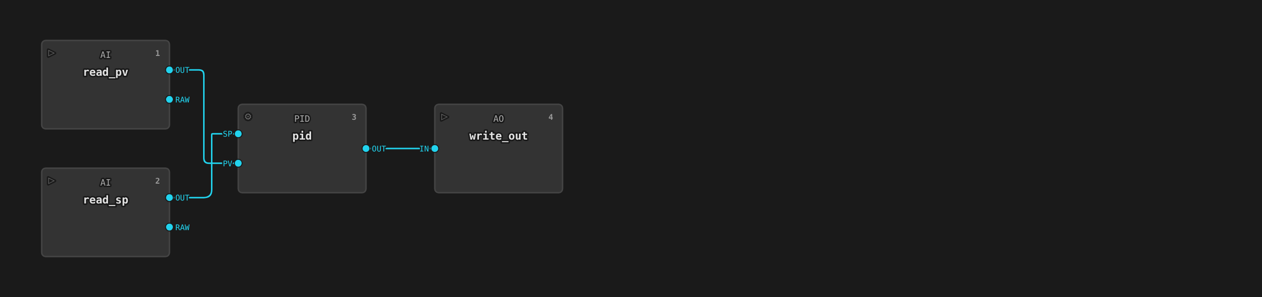
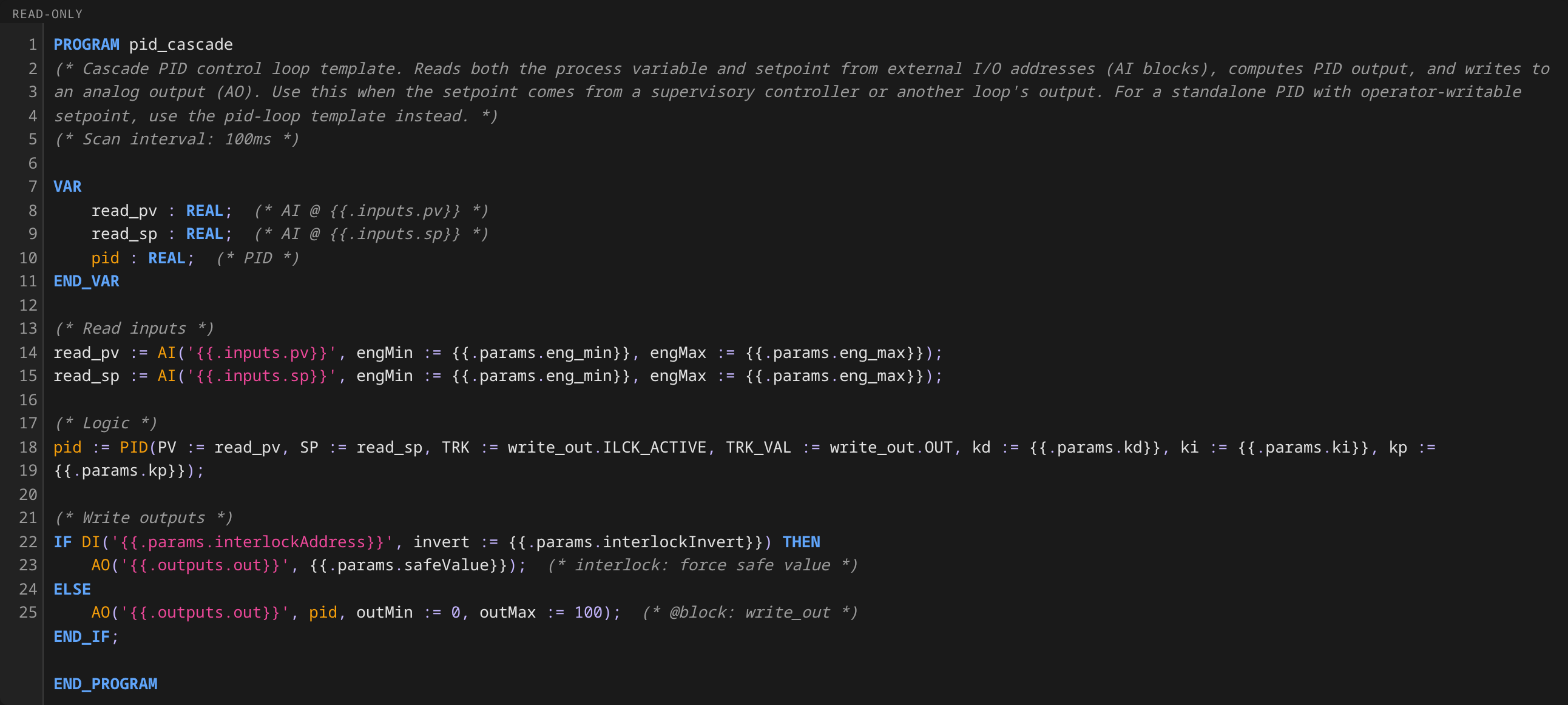
- Reads
PVfrom thepvinput tag address. - Reads
SPfrom thespinput tag address (the outer-loop output, or a supervisory target). - Computes PID output against the error
SP − PV. - Writes
CV(0–100%) to theouttag address.
Tuning advice is identical to pid-loop. See its
tuning section. Both loops use the same PID
block, which clamps its own output and backs the current scan's error
back out of the integral whenever that clamp engages (see pid-loop's
"How it works"). Neither the inner nor the
outer integrator keeps accumulating once its own CV saturates.
As with pid-loop, when the device interlock is enabled and trips, the
template freezes the integrator (TRK) and back-calculates it from the
output's actually-written value (TRK_VAL). The inner loop tracks
what the device really sees and resumes bumplessly on release. The same
back-calculation mechanism is how a cascade inner loop initializes from
its real output. Wire the outer loop's TRK_VAL from the inner loop's
setpoint source so the outer loop hands off without a bump when it takes
over (see the wiring pattern below).
Manual mode drives the inner loop's CV directly, the same
mechanism pid-loop documents: with the inner loop's equipment in
Manual mode, writing CV overrides the PID block's own output, and the
block tracks the override the same way it tracks a device-forced value
above, bumpless in both directions. Automatic mode refuses the write
and, on return to Automatic, hands control back to the loop's own
computation with no extra step. This is independent of the outer loop.
Switching the inner loop to Manual overrides only its own CV. It does
not touch the outer loop's setpoint output.
A setpoint that stops arriving
The supervisory setpoint is an analog input, so it fails the way any
instrument fails. read_sp refuses to publish a reading it does not
trust. It holds SP at the last trusted value and raises SP_BAD. It
also faults, which puts the control program into Degraded with
read_sp named.
The loop keeps regulating. It does not hold its output the way it
does on a bad PV, and that asymmetry is deliberate
(ADR 0074).
A dead PV blinds the loop, so it has no basis on which to act. A dead
SP leaves the measurement live and the valve live, and takes away only
the target. Freezing the output there would throw both working things
away and leave the process open loop against whatever disturbs it, on
what is usually a transient supervisory link failure. Holding the last
cascade setpoint and continuing to control is the standard answer.
So SP_BAD is annunciation, and it is the whole of the automatic
response. What to do about it is an operator decision:
- Leave it. The process stays at the last target the supervisor asked for, which is often the right place for it.
- Take the inner loop to Manual and drive
CVdirectly, the commissioning path above. - Alarm on it. Declare a
TagTrueAlarmDefinition onSP_BADso the condition annunciates. On its own it only sits on a faceplate. A batch that must not run to a frozen target holds on the alarm.
Where the driver reports no quality of its own, set spRawFailLow and
spRawFailHigh on the instance, or SP_BAD never goes true. On a card
whose range diagnostic this product knows the driver already reports a
broken wire and no band is needed. A card that maps 4 mA onto raw zero
admits no band that would separate one. See the process-variable band in
pid-loop for why.
Cascade wiring pattern
Typical pairing:
- Outer loop —
pid-loopdriving the cascade setpoint.CVof the outer loop is written (via an analog output address, or directly via an internal tag) to the same tag address that the inner loop reads assp. - Inner loop —
pid-cascade, taking its SP from that address.
The outer-loop scan rate should be slower than the inner's, typically 2–10×. A reactor temperature / jacket temperature cascade might run the outer loop at 1 s and the inner at 100 ms.
Failure modes
- SP source tag goes stale / offline —
pid-cascadecontinues regulating to the last-read value, by design.SP_BADis what makes that visible. See "A setpoint that stops arriving" for the remedies. An AlarmDefinition on IOModuleStateEquals: Offlinecovers the case where the whole supervisory module drops.SP_BADalone does not distinguish that from a single dead channel. - Outer loop saturated long-term — SP pinned at its limit means the cascade can't deliver what the supervisory loop wants. Fix by revisiting outer-loop tuning or actuator sizing. Raising inner gains fixes nothing here.
Reference instances
| Deployment | Unit | Instance | Purpose |
|---|---|---|---|
| newark-plant | granulator-1 | jacket-temp-ctrl |
Granulator bowl jacket temperature tracks the recipe-driven SP written by the outer temperature loop |
The reference plant currently has no pid-cascade instances. It uses pid-loop
for its single closed loop (N2 blanket pressure). Add a pid-cascade
when demonstrating reactor-jacket cascade control.
Try it
On newark-plant:
- Process → newark-plant → granulator-1
- Click jacket-temp-ctrl on the unit detail view
- Observe
PV,SP, andCV— note thatSPis read-only on the faceplate - Write to the
Granulator1.JacketTempSPaddress (via the outer loop or an operator override) and watch the cascade track