Control Module: pid-loop
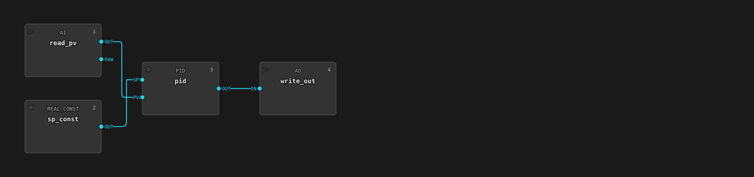
A single-loop PID controller. Reads a process variable from an analog input, holds the setpoint in an operator- or recipe-writable register, computes a PID control output, and writes that output to an analog output. Use this template for any self-contained regulatory control loop where the setpoint comes from an operator or a recipe step.
For cascade control where the setpoint is driven by another controller
or a supervisory system, use the pid-cascade template instead.
Where to find it
System endpoint → Equipment Library → Control Modules tab → select pid-loop.
What you see on the faceplate
Clicking a pid-loop instance on the unit detail view opens a faceplate with:
| Element | Meaning |
|---|---|
| PV | Process variable (read-only) |
| SP | Setpoint (writable in Manual mode) |
| CV | Control output percentage, 0-100 (writable in Manual mode) |
The faceplate shows ISA-88 mode. In Manual mode an operator can write
the setpoint directly, or drive CV directly for the commissioning
workflow below. In Automatic mode a recipe step owns the setpoint and
the PID block owns CV. Both writes are refused.
Tags
The template declares deviceClass: controller and a role on each tag
(ADR 0016). The HMI renders
from these declarations and never infers meaning from moduleType or
tag names. SP (role: setpoint) fills
the HMI setpoint bar. PV (role: feedback) fills the feedback bar
and, with no role: state tag, is the card's prominent value. CV
(role: command) renders as the commanded output.
| Tag | Type | Access | Role | Description |
|---|---|---|---|---|
PV |
Float | read | feedback |
Measured process variable, scaled to engineering units. Shown as the card's prominent value. |
SP |
Float | read/write | setpoint |
Setpoint. Operator or recipe writes this. |
CV |
Float | read/write | command |
Control output (0-100%) driven to the analog output. Writable only in Manual mode — see "How it works" for what a write does. |
ILCK |
Boolean | read | interlock |
true while the device interlock is forcing the output to its safe state. Reserve a TagTrue AlarmDefinition for interlocks whose trip is abnormal in itself (why). The historian records every trip either way. |
PV_BAD |
Boolean | read | alarm |
true while the process variable is not trusted: the driver reported bad quality, the read failed, or the raw value fell outside the fail band. PV holds its last trusted reading while this is set, and the loop holds its output. A TagTrue AlarmDefinition on this is worth having on any loop whose instrument can fail. |
Parameters
| Parameter | Default | What it does |
|---|---|---|
kp |
1.0 |
Proportional gain |
ki |
0.1 |
Integral gain |
kd |
0.01 |
Derivative gain |
eng_min / eng_max |
(blank) | Process variable scale range |
eng_units |
(blank) | Display units for PV and SP |
interlockAddress |
(empty — interlock disabled) | Device address of a boolean trip signal, read by the output block every scan; while tripped (or unreadable — fail-safe) the output is forced to the safe value. |
interlockInvert |
false |
Trip while the signal is false (with the invert off, true trips). |
safeValue |
(empty) | Output value forced while interlocked. Empty means the output range minimum. |
rawFailLow / rawFailHigh |
(blank — no band) | Raw counts outside which the input reading is rejected and PV_BAD is raised. Both or neither. Leave blank wherever the driver already reports quality of its own, which is OPC UA, simulation, and a Modbus card whose range diagnostic this product knows — see "How it works" for what a band can and cannot detect. |
Setting interlockAddress on an instance enables the device interlock.
See Alarms and Interlocks → Pattern 0.
The scan interval is fixed at 100 ms, faster than other analog templates because closed-loop PID needs tighter response.
How it works
Each scan, the runtime:
- Reads the process variable from the analog input.
- Computes PID output against the current setpoint using
kp,ki,kd. - Writes the resulting
CVto the analog output, clamped to 0-100%.
The PID block uses a standard parallel form. Tune gains in the detail
view's Parameters section. The PID block also clamps its own output
to outMin/outMax (0-100% by default) and, whenever that clamp
engages, backs the current scan's error back out of the integral. The
integrator stops growing once CV saturates. This clamping anti-windup
is built into the block itself. There is no output rate limiting in
this template. If you need that, derive a new template from this one.
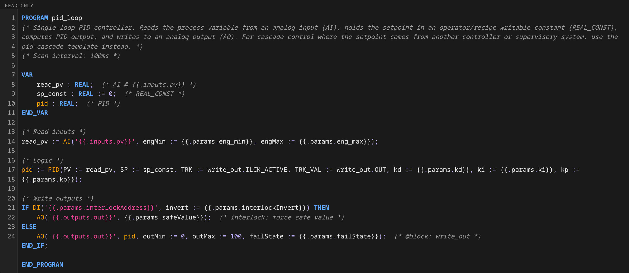
When the device interlock is enabled (see interlockAddress above) and
trips, the analog output is forced to its safe value. The template wires
the output block's interlock state into the PID's TRK input (freezing
the integrator) and the output block's actually-written value into the
PID's TRK_VAL input (back-calculation output tracking). While forced,
the PID tracks the value the device really sees. When the interlock
releases, the loop resumes from the real output, a bumpless transfer.
Without the tracking it would resume from a wound-up state. This is
inert unless the interlock is enabled, so existing instances are
unaffected.
A process variable the block cannot trust holds the loop. A broken
4-20 mA wire is still a successful read of a register, and the register
holds a value near the bottom of span. Scaled naively that is an
ordinary reading of about 0 %, the error against any setpoint above it
is close to maximal, and the loop answers by driving the valve to the
opposite rail. So the input block does not publish a reading it does
not stand behind. It holds PV at the last trusted value, raises
PV_BAD, and faults itself so the control program reports Degraded
with the block named. The template wires PV_BAD into the PID, which
holds its output at the value it actually wrote and resumes bumplessly
when the instrument comes back.
Two things decide whether a reading is trusted. The driver may report
it, which needs no configuration. That happens on OPC UA, in
simulation, and on a Modbus card whose own range diagnostic this
product knows. A WAGO 750-454 states a broken wire in the low bits of
the same word that carries the measurement, and the driver reports the
bit the card set. Or the raw value may fall outside rawFailLow and
rawFailHigh, which is what remains where the driver reports nothing.
A band is not a rule of thumb, and it is not always available. It separates a dead transmitter from a live one only where the values a failure produces lie outside the interval genuine readings occupy. A card that maps 4 mA onto raw zero does not do that. The 750-454 carries its measurement in the top thirteen bits, so a genuine reading is a multiple of eight. Its broken-wire code is raw 3, which falls strictly between the genuine readings 0 and 8. A band accepts a closed interval, so no pair of bounds rejects the fault while accepting both of its neighbours. The band cannot express the condition at any setting. That card needs none, because the driver already reports its bits. Set a band only from numbers measured on the specific card, and only where those numbers separate. Full reasoning: ADR 0074 and its #1740 amendment.
Manual mode drives CV directly. With the equipment in Manual mode,
writing CV overrides the PID block's own output. The write reaches
the analog output on the next scan, bypassing the PID computation
entirely. Automatic mode refuses the write (ISA-88 Table 1: the control
algorithm owns the equipment). The PID block tracks a Manual CV
override the same way it tracks a device-forced value above, bumpless
in both directions, with no separate mechanism. Switching back to
Automatic hands control back to the loop's own computation with no
extra step. The operator's last-driven value is what the loop resumes
from.
Tuning
The pid-loop template ships with conservative default gains that work
on the simulator but will need adjustment for any real loop. This section
covers the practical commissioning workflow: the steps you'd actually
follow on a new equipment area. It teaches no vendor-specific tuning
method.
Parallel form
The template implements the standard parallel form:
CV(t) = kp·e(t) + ki·∫e(t)dt + kd·de(t)/dt
where e = SP - PV. This is different from the ideal (also called
"dependent") form some vendors use, where ki and kd are expressed as
time constants relative to kp (e.g. Ti = kp/ki, Td = kd/kp). If
you're porting tuning constants from another system, check which form
the source used and convert before pasting.
What each gain does, in isolation
Walk a new loop one gain at a time:
| Gain | Bump it up if | Bump it down if |
|---|---|---|
| kp | The PV is consistently short of setpoint | The PV oscillates around setpoint |
| ki | The PV reaches setpoint slowly and parks just below | The PV overshoots and takes forever to settle |
| kd | A step disturbance causes a long, slow recovery | The PV jitters on noisy input |
For most loops, start with kp only (ki = 0, kd = 0), get the loop
to track without oscillating, then add a small ki to eliminate the
steady-state offset, then add kd only if you genuinely need faster
disturbance rejection. Many pharmaceutical loops never use kd.
Practical commissioning workflow
- Open the trend chart on this loop's
PV,SP, andCVtags via the Data endpoint → Trends view. Keep all three on the same chart. - Switch to Manual mode from the faceplate. The operator owns
CVdirectly. - Step the CV by 10–20 % and watch how
PVresponds:- Time to first response: how long before
PVstarts moving? That's your dead time. - Time to peak / steady state: how long until
PVsettles at a new value? - Process gain: by how much did
PVchange per 1 % ofCV?
- Time to first response: how long before
- Set initial
kpto roughly0.5 / process_gainandkito1 / (4 × time_to_steady_state). These are conservative starting values that almost never cause oscillation. - Switch back to Auto from the faceplate. Set the recipe-driven
setpoint and watch
PVtrack. Use the trend chart to verify:- No sustained oscillation. A few cycles of damped oscillation
after a setpoint change is fine. Never-decaying oscillation means
kpis too high. - Reaches setpoint within a reasonable time. "Reasonable" depends on the process: minutes for a reactor jacket, seconds for a flow loop.
- No persistent offset. If
PVparks consistently above or belowSP, you need moreki.
- No sustained oscillation. A few cycles of damped oscillation
after a setpoint change is fine. Never-decaying oscillation means
- Iterate in steps of ±25 % on each gain. Don't change two gains at once. You won't know which one caused the change.
When to escalate
The single-loop pid-loop template is intentionally simple. Move to a
different template (or derive a new one) when you need:
- Cascade control — outer-loop setpoint drives an inner-loop
setpoint. Use
pid-cascadeinstead. Common pattern: outer loop is reactor temperature, inner loop is jacket temperature. The outer-loop output becomes the inner-loop SP. - Output rate limiting — for loops driving slow actuators, a CV rate limit prevents the controller from commanding faster moves than the actuator can follow.
- Feedforward — adding a measurable disturbance signal directly into the CV calculation, ahead of the feedback path.
For each of these, the right move is to derive a new control-module
template. Keep the same pid-loop interface (PV, SP, CV) so existing
phase templates that bind to a pid-loop role can use the new template
without modification.
What good tuning looks like on the trend chart
A well-tuned loop, after a setpoint change, shows:
- One small overshoot of 5–10 % of the SP step
- Damped oscillation that disappears within 2–3 cycles
- No persistent offset between
PVandSPafter settling CVmovement proportional to deviation, no rapid hunting
Bad signs to look for:
- Sustained oscillation —
kptoo high orkitoo high - Slow drift toward setpoint —
kitoo low CVsaturated at 0 % or 100 % for long periods — the loop is asking for more authority than the actuator can deliver. Either the process is undersized or there's a hardware fault. Adding morekpwon't help. Fix the equipment or escalate to cascade with a faster inner loop.- Noisy
CV—kdtoo high on a noisyPVsignal. Trykd = 0first. Addkdonly oncekpandkiare stable.
The faceplate trend view shows PV, SP, and CV together so you can
diagnose all of these visually without exporting data.
Reference instances
| Unit | Instance | Purpose |
|---|---|---|
| mix-tank-1 | N2 blanket pressure controller | Holds tank headspace pressure at target during fills and transfers |
The reference plant uses only one pid-loop instance. Most temperature and
agitator control in the reference plant is handled by analog-control (feedback +
deviation alarm). Closed-loop PID is the exception there.
Try it
- Process → riverbend → pharma-area → sim-cell → mix-tank-1
- Click the N2 blanket pressure symbol on the unit detail view
- On the faceplate, write a new setpoint (
SP) — e.g. change from0.2bar to0.3bar - Watch
PVconverge on the new setpoint andCVsettle at the steady-state output - Open a trend chart with
PV,SP, andCVon the same chart to see the loop response