Control Module: analog-control
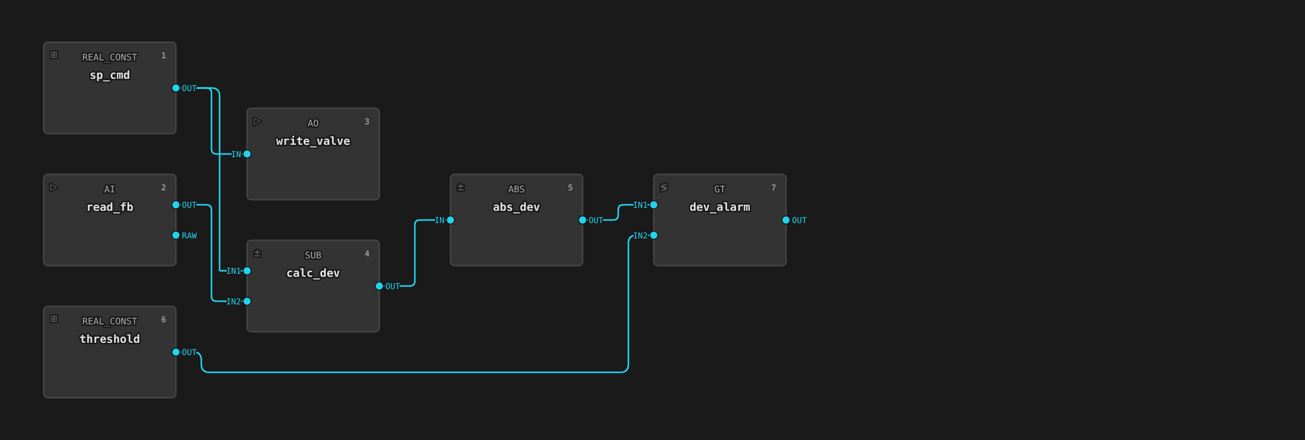
A modulating analog output with feedback and deviation alarm. The
operator or recipe writes a commanded position to CMD. The runtime
drives an analog output to the field and reads back the actual position
via an analog input. A deviation alarm trips when the actual value
differs from the commanded value by more than a configurable threshold.
Use this template for modulating valves, variable-speed motors, heaters,
and any other continuously-variable actuator.
Where to find it
System endpoint → Equipment Library → Control Modules tab → select analog-control.
What you see on the faceplate
Clicking an analog-control instance on the unit detail view opens a faceplate with:
| Element | Meaning |
|---|---|
| CMD | Commanded position or speed (writable) |
| POS | Actual position or speed feedback (read-only) |
| DEV_ALARM | Deviation alarm — true when |CMD − POS| exceeds dev_threshold |
The faceplate shows ISA-88 mode. In Manual mode an operator can write
CMD directly. In Automatic mode only recipe logic does.
Tags
The template declares deviceClass: actuator and a role on each tag
(ADR 0016). The HMI renders
from these declarations and never infers meaning from moduleType or
tag names. The CMD tag's role: setpoint
fills the HMI setpoint bar. POS (role: feedback) fills the feedback
bar and, since this template declares no role: state tag, doubles as
the card's prominent value.
| Tag | Type | Access | Role | Description |
|---|---|---|---|---|
CMD |
Float | read/write | setpoint |
Commanded position (0-100% by default). Recipe or operator writes this. |
POS |
Float | read | feedback |
Actual position feedback read from the field. Shown as the card's prominent value. |
DEV_ALARM |
Boolean | read | alarm |
true when absolute deviation exceeds dev_threshold. Typically wired into an Alarm CRD. |
ILCK |
Boolean | read | interlock |
true while the device interlock is forcing the output to its safe state. Reserve a TagTrue AlarmDefinition for interlocks whose trip is abnormal in itself (why). The historian records every trip either way. |
Parameters
| Parameter | Default | What it does |
|---|---|---|
dev_threshold |
5.0 |
Deviation band in engineering units |
eng_min / eng_max |
(blank) | Position scale range |
eng_units |
(blank) | Display units (%, rpm, °C, etc.) |
interlockAddress |
(empty — interlock disabled) | Device address of a boolean trip signal, read by the output block every scan; while tripped (or unreadable — fail-safe) the output is forced to the safe value. |
interlockInvert |
false |
Trip while the signal is false (with the invert off, true trips). |
safeValue |
(empty) | Output value forced while interlocked. Empty means the output range minimum. |
Setting interlockAddress on an instance enables the device interlock.
See Alarms and Interlocks → Pattern 0.
The former state_tag parameter is replaced by the per-tag role
declarations (POS carries role: feedback and is shown as the card's
prominent value).
The scan interval is fixed at 200 ms.
How it works
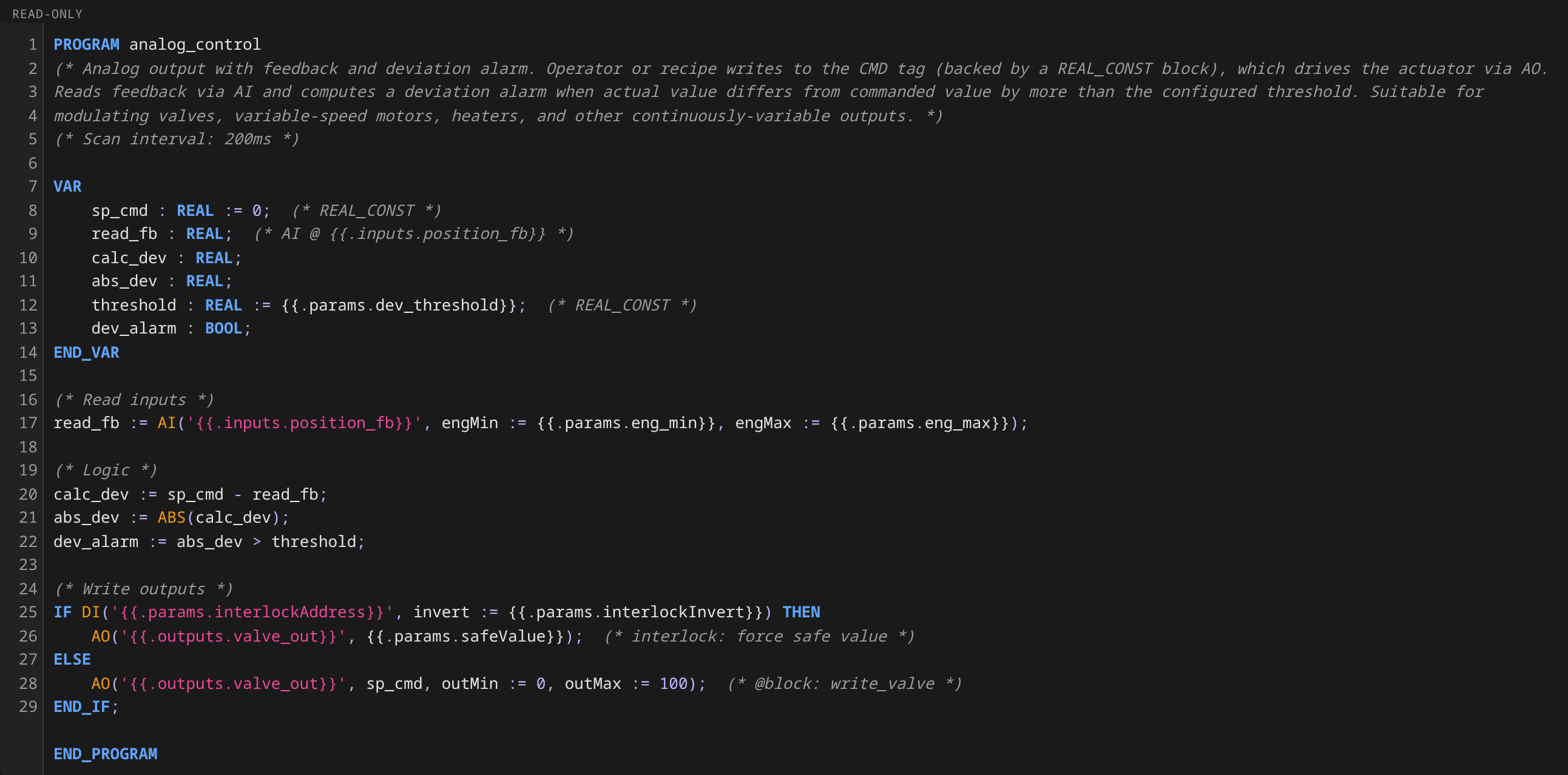
Each scan, the runtime:
- Writes
CMDto the analog output. - Reads the analog input into
POS. - Computes
|CMD − POS|and compares againstdev_threshold. - Sets
DEV_ALARMif the absolute deviation exceeds the threshold.
The deviation check has no debounce. For actuators with slow response
times (temperature controllers, large valves), wire DEV_ALARM into an
AlarmDefinition with condition.type: TagTrue and a debounceSeconds
window. More commonly, wire the underlying POS/CMD tags into
a TagDeviation rule with both deadband and debounceSeconds set.
See Alarms and Interlocks
for the full pattern.
Reference instances
The reference plant uses analog-control for every modulating actuator:
| Unit | Instance | Purpose |
|---|---|---|
| reactor-1 | jacket temperature controller | Reactor temperature control via jacket |
| reactor-1 | agitator motor | Variable-speed reactor agitator |
| reactor-1 | solvent inlet valve | Modulating solvent feed |
| reactor-1 | outlet valve | Modulating transfer to filter-dryer |
| reactor-1 | reagent inlet valve | Modulating reagent feed |
| mix-tank-1 | agitator motor | Variable-speed tank agitator |
| mix-tank-1 | temperature controller | Tank temperature control |
| filter-dryer-1 | jacket heater controller | Vacuum-dry heater control |
| filter-dryer-1 | vacuum pump controller | Vacuum pump speed control |
| filter-dryer-1 | smoother / agitator motor | Variable-speed cake smoother |
Try it
- Process → riverbend → pharma-area → sim-cell → reactor-1
- Click the agitator motor symbol on the unit detail view
- On the faceplate, write a new value to
CMD(e.g.50for 50%) - Watch
POSramp toward the new commanded value.DEV_ALARMmay flicker true during the ramp ifdev_thresholdis tight relative to ramp time